910-0001-00-INS -R02 Page 25 of 53
Information contained in this document pertains to a Canadian origin product that is controlled as "dual use" by the Canadian government. However, when in
the United States or possessed by a US person, it may be considered a defense article from the US Government's perspective. US government authorization
may be required for re-transfer to a foreign person. If you have any questions, please contact FLIR's Global Trade Compliance group at
exportquestions@flir.com .
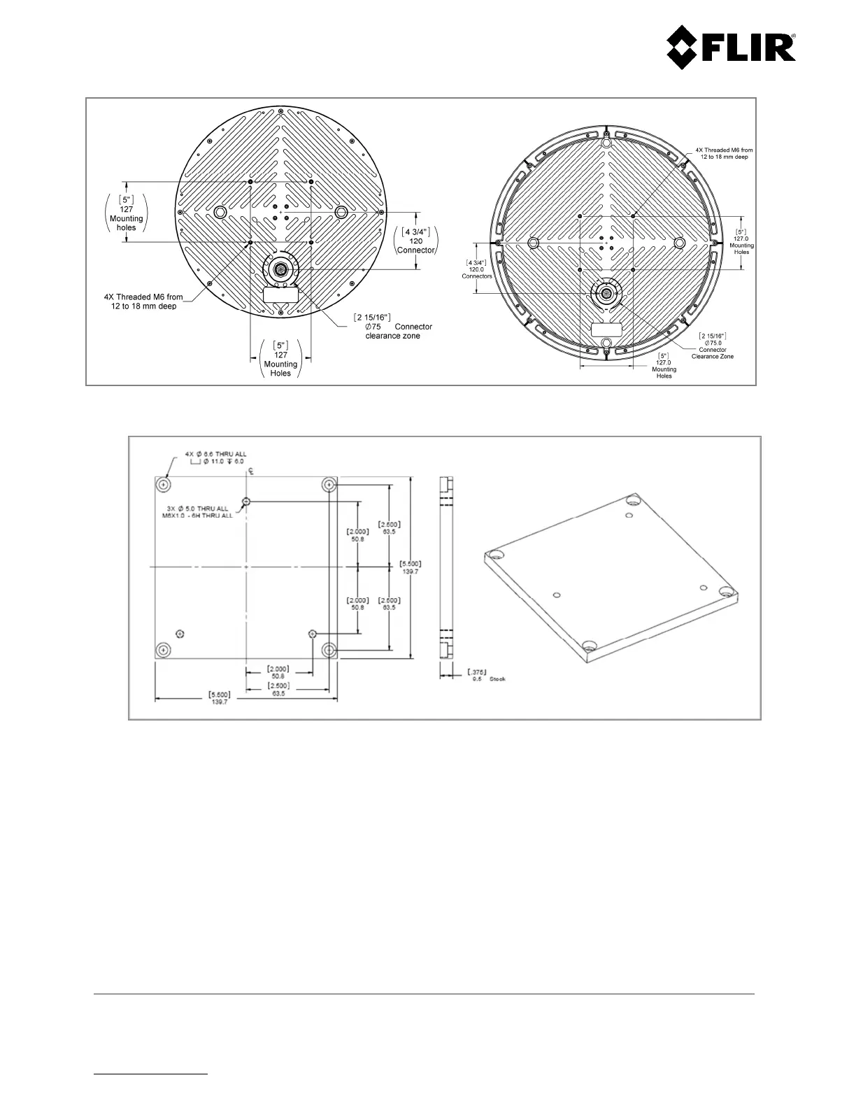
Figure 16 – Left - R1, R2, R3 and R3D; Right - R5 and R5D: Mounting and Connector Location
Figure 17 - Regular Mounting Plate Outline
4.1.2 Radar Mounting
The radar mount must provide stability and rigidity in order to support the weight of the R1, R2, R3, R3D, R5
and R5D radars. This way, the unit maintains consistent stable radar images and readings, which are critical to
the performance of the system. Securing the radar requires four M6 screws. In selecting or designing the
mount, high wind speed conditions must be considered.
 Loading...