910-0001-00-INS -R02 Page 36 of 53
Information contained in this document pertains to a Canadian origin product that is controlled as "dual use" by the Canadian government. However, when in
the United States or possessed by a US person, it may be considered a defense article from the US Government's perspective. US government authorization
may be required for re-transfer to a foreign person. If you have any questions, please contact FLIR's Global Trade Compliance group at
exportquestions@flir.com .
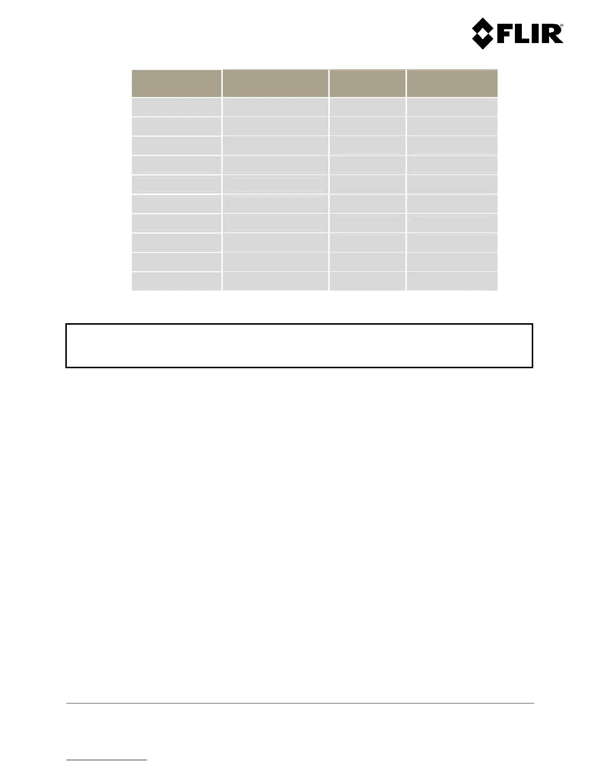
Pin Function Pin Function
A ETHERNET TX +
L
ETHERNET RX -
B Unused
M
ETHERNET RX +
C Unused
N ETHERNET TX -
D Unused
P Unused
E Unused
R Unused
F Unused
S Unused
G Unused
T Unused
H Unused
U Unused
J FEED +28 V
V Unused
K RETURN +28 V *
Table 7 - Power / Data Connector Pin Assignment – R1, R2, R3, R3D, R5 and R5D
Note
RETURN +28V has the same meaning as the
(minus) terminal on a battery. The cable connect
the radar should use the appropriate mating connector (FLIR Radars Part # 401-1015).
4.4 NETWORK INFRASTRUCTURE INSTALLATION
Ensure installing the network components per the manufacturer’s recommendations.
The recommended Ethernet cabling for connecting network components is Cat 5e or Cat 6. The IEEE 802.3
standard specifies that the maximum cable length is to be 100 meters (328 feet) between two Ethernet
devices for 10 and 100 Mbps links.
 Loading...