EasyManua.ls Logo

Floe INSTA-FLOAT - User Manual

Default Icon
4 pages
Print Icon
To Next Page IconTo Next Page
Loading...
STEP ONE
Position the floating transporter at the entrance of your
FLOE
lift system as pictured in
Fig. 1. Face transporter so that the attached tow cable is in the direction in which the lift will
be pulled.
Note: If your lift is on a trailer and being installed for the first time, have the lift positioned so that
you can back your trailer into the water and roll your lift off until it floats.
STEP TWO
Raise the lift bed to its maximum height, and position the transporter within the lift
(Fig. 2). Typically, the side of your lift that has either a winch, hydraulic system, or a VSD
motor is heavier.
TO COMPENSATE:
If you have a lift with a winch, simply slide the Insta-Float Transporter off-center approximate-
ly 6” towards the heavy side.
If you have a hydraulic or VSD lift, position the transporter tight to the heavy side. Doing this
will keep the lift close to level while you float it into position.
Note: If you have a hydraulic lift and need additional bed height to fit the floating transporter between
the top and bottom beams, either manually lift the bed up higher, or use the transporter’s winch sys-
tem to raise it higher. With its handle facing outward, attach the winch transporter’s clamp to the
hydraulic assembly’s topmost beam and its hook to the cradle lift platform beam. You may also need
to do this when removing the transport system once the lift is installed.
STEP THREE
Lower the lifting bed down onto the aluminum framework of the transporter unit.
(Step 3/Fig. 3).
IMPORTANT WARNING
* IF YOU HAVE A WINCH MODEL LIFT, release all but one wrap of
cable from the lift winch drum (Fig. 4) before proceeding to Step 4.
* IF YOU HAVE A VSD POWERED LIFT, lower the lifting bed as low
as possible (until it is stopped by the limit switch).
* IF YOU HAVE A HYDRAULIC POWER LIFT, extend the hydraulic
cylinder to its maximum length before proceeding to Step 4.
WARNING: EXTENDING THE HYDRAULIC CYLINDER MAY CAUSE THE LIFTING CABLE (LOCATED
AT THE END OF THE HYDRAULIC CYLINDER) TO SLIP OUT OF THE UPPER PULLEY. IT IS IMPOR-
TANT THAT THIS LIFTING CABLE BE POSITIONED WITHIN THE PULLEY BEFORE RAISING THE PLAT-
FORM AGAIN.
THE “INSTA-FLOAT” BY FLOE
THE ULTIMATE BOAT LIFT INSTALLATION AND REMOVAL SYSTEM
FOR BOAT LIFTS USING TWO PRE-INSTALLED PAIRS OF FLOE’S
BOAT LIFT WHEEL KITS
PLEASE READ AND FOLLOW ALL INSTRUCTIONS & WARNINGS
Failure to do so may result in damage to your lift system, personal injury, or death.
WARNING: Prior to using your “Insta-Float System,” it is recommended that the
canopy fabric be removed from your lift as potential problems could occur if winds
are present. (Note: Canopy frame/structure can remain attached.)
STEP 1-2/Figure 1
STEP 2/Figure 2
STEP 3/Figure 3
P/N
611-03300-00
Issue Date: 04/29/05 Rev: 10/19
Figure 4
Question and Answer IconNeed help?

Do you have a question about the Floe INSTA-FLOAT and is the answer not in the manual?

Summary

Insta-Float System Setup: Step One

Positioning the Transporter

Position the floating transporter at the lift entrance, facing the direction of pull.

Insta-Float System Setup: Step Two

Raising Lift Bed and Transporter Placement

Raise lift bed to maximum height and position transporter within the lift, compensating for heavy side.

Compensating for Lift Weight

Adjust transporter position for winch, hydraulic, or VSD lifts to maintain level lift.

Adjusting for Clearance

Manually adjust bed height or use transporter winch for clearance; attach clamp and hook.

Insta-Float System Setup: Step Three

Lowering Lift Bed onto Transporter

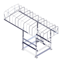
Lower the lift bed down onto the aluminum framework of the transporter unit.

Pre-Step Preparations and Warnings

Prepare winch, VSD, or hydraulic lift and ensure lifting cable is correctly positioned.

Insta-Float System Setup: Step Four

Installing Transporter Winch System

Install transporter winch on the beam opposite the main lifting cable, ensuring proper orientation.

Attaching and Securing Winch Hook

Attach hook to lower frame beam and crank winch to raise lift onto transporter wheels.

Critical Hook Positioning Warning

Ensure hook is properly positioned and tight to the beam before tightening the winch cable.

Lift Platform Raising Warning

Never raise lift platform with transporter winch installed to avoid severe damage or injury.

Insta-Float System Setup: Step Five

Readiness for Water Movement

The lift system is now ready to be rolled into water or floated.

Insta-Float System Setup: Step Six

Positioning and Lowering onto Pads

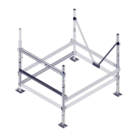
Move lift to location, then lower onto leveling pads by cranking the transport winch.

Leveling the Lift System

Level lift to within two inches; float back up if out of level and adjust pads.

Leveling Pad Adjustment Caution

Caution: Do not loosen adjustment bolts more than two revolutions to avoid disengagement.

Insta-Float System Setup: Step Seven

Disconnecting Transporter and Removal

Disconnect transporter winch system; raise lift platform to float transporter out.

Hydraulic Lift Height Adjustment

Refer to Step 2 for additional height needed for hydraulic lift transporter removal.

Insta-Float Lift Removal

Repeating Setup Steps for Removal

Repeat previous steps for lift removal. Retract leveling legs while floating.

Marking Leveling Legs for Future Use

Mark leveling leg height for easier leveling in subsequent years.

Insta-Float Bill of Materials

Parts List for Insta-Float (Without Winch)

List of parts and quantities for the Insta-Float system, excluding winch components.

Floe INSTA-FLOAT Specifications

General IconGeneral
BrandFloe
ModelINSTA-FLOAT
CategoryBoating Equipment
LanguageEnglish

Related product manuals