This document provides replacement instructions for the VSD Cover & Base for FLOE Docks & Lifts, covering various VSD models.
Function Description
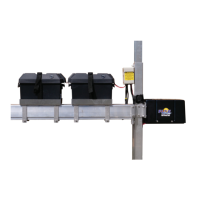
The VSD Cover & Base are components of the Variable Speed Drive (VSD) power unit used in FLOE Docks & Lifts. The VSD unit is responsible for controlling the lifting and lowering operations of the boat lift. The replacement kit includes a new cover with decals, a base with speed nuts, base screws, lower support foam, foam spacers, and anti-seize compound, ensuring proper protection and support for the internal motor and electrical connections.
Important Technical Specifications
The replacement instructions cover several VSD models, each with specific part numbers:
- VSD3800-5000 (DC VSD): P/N 511-38585-01 (Kit includes cover & base replacement for 3.8-5K DC)
- VSD3800-5000 (AC VSD): P/N 511-38590-00 (Kit includes cover & base replacement for 3.8-5K AC)
- VSD6000-10,000 (DC VSD): P/N 511-60785-01 (Kit includes cover & base replacement for 6-10K DC)
- VSD6000-8000 (AC VSD): P/N 511-60790-00 (Kit includes cover & base replacement for 6-8K AC)
The replacement process involves specific torque settings for re-installing the motor plate bolts, which should be tightened to 10 ft-lb.
Usage Features
The VSD power unit, protected by the cover and base, facilitates the operation of FLOE boat lifts. Key usage features include:
- Variable Speed Control: Allows for smooth and precise control over the lift's movement.
- Compatibility: Designed to integrate seamlessly with various FLOE lift models (3800-10,000 series).
- Protection: The cover and base protect the internal motor and electrical components from environmental elements, ensuring longevity and reliable operation.
- Safety: The system incorporates safety features such as lower limit switches to prevent over-lowering and instructions to ensure no load is on the lift during maintenance.
Maintenance Features
The document outlines a detailed procedure for replacing the VSD cover and base, emphasizing several maintenance features:
- Pre-Maintenance Safety: Crucially, the lift must be lowered until the cradle reaches the lower limit switch and the boat's weight is off the lift. Ideally, the boat should be removed and tied to the dock. For AC drive motors, the power cord must be unplugged from the ASC (Automatic Shoreline Charger) before proceeding. This ensures safety and prevents the drive unit from spinning rapidly if the lift is not fully lowered.
- Tools Required: A specific set of tools is needed for the replacement, including:
- (2) 9/16" sockets/wrenches
- 5/32" or 1/4" hex bit/Allen wrench (depending on VSD model)
- 5/16" flat tip screwdriver
- Torque wrench
- Pry bar (if the motor is seized into the coupler)
- Step-by-Step Replacement: The instructions provide clear steps for removal and re-installation:
- Cover Removal: Remove screws from the bottom of the motor cover, pull down the cover, and disconnect motor and brake wires. For AC units, disconnect the plug from the ASC.
- Drive Unit Removal: Remove fasteners securing the drive unit to the ball screw clamp. If the drive unit is seized, use a pry bar to carefully dislodge it.
- Base and Foam Removal: Remove remaining screws securing the base to the cover and remove foam inserts.
- Motor Mount Removal: Remove fasteners securing the motor mount to the cover. Note that these bolts are reused.
- Motor and Foam Replacement: Remove old foam from the motor and replace it with new included foam, ensuring proper adhesion with double-sided tape. Place the new cover over the motor, aligning mounting holes, and install included spacers.
- Motor Plate Re-installation: Replace the motor plate and previously removed bolts, torquing them to 10 ft-lb.
- Foam Insert Placement: Replace foam inserts, ensuring they are kept away from the heater band for AC drive units.
- Base Re-attachment: Place the base onto the bottom of the cover and secure it with two screws.
- Electrical Re-connection: Re-attach motor and brake connectors (DC units) or the plug from the ASC (AC units).
- Final Cover Re-attachment: Re-install the two screws at the bottom of the drive unit cover.
- Anti-Seize Application: The entire contents of the anti-seize packet must be applied to the motor shaft of the drive unit before installation onto the ball screw. This prevents seizing and ensures smooth operation.
- Gap Specification: When re-installing the drive unit, fasteners should be tightened until there is a 1/8" gap between the motor plate and the ball screw clamp, ensuring proper alignment and function.
- Component Reuse: Emphasizes that certain bolts (from the motor mount) are to be re-used, preventing unnecessary waste and ensuring compatibility.
- Information Access: Directs users to the owner support tab on the FLOE website for additional information, indicating ongoing support and resources.