9
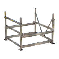
Limit Switch
Ball Nut
Galvanized
Steel
Lifting Cable
Rotating Screw
The drive train simply spins
the
screw so that the ball nut
travels
back and forth as it
pulls the lifting cable.
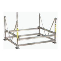
Fig. 3
DRIVE TRAIN & BALL SCREW
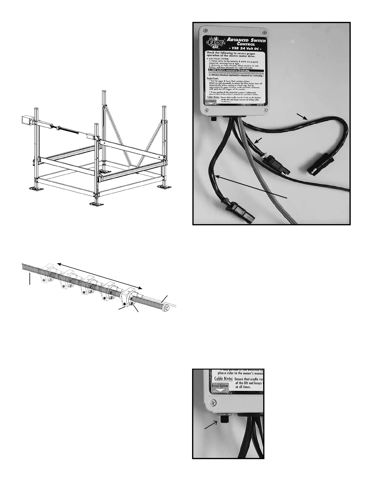
This boat lift is equipped with FLOE’s exclusive
Vertical Screw Drive (VSD) drive train technolo-
gy. The VSD system replaces the common winch
style drive-train common to most
boat lifts. It uses a DC or AC powered, high-torque
electric motor along with a ball-screw and ball-nut
mechanism. See Fig. 2.
When operated, the motor turns the ball-screw,
allowing the ball-nut to travel back and forth
along the screw. This raises and lowers the lift as
shown in Fig. 3.
Maintenance and trouble-shooting tips for the
exclusive drive-train system are addressed later
in this manual.
This efcient drive train has enabled FLOE to
design a lift for mid-sized boats that is easily
powered by a 24-Volt battery system or a 120-
Volt AC power system, and to develop a line of
optional accessories to keep the batteries charged
effortlessly.
To prepare your VSD lift for operation, you should
rst understand the basics for setting up the
electrical features of the lift, and especially the
importance of the limit switch safety feature.
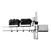
Fig. 2
Drive Train
Power Unit
& Ball Screw
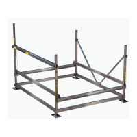
ADVANCED SWITCH CONTROL (ASC)
The electrical connection panel (Fig. 4) is located
on a separate box. It is designed to allow for easy
hook up of standard and optional components as
well as the resetting of tripped circuits.
• The black wire is for the limit switch.
• The blue wire is for the wired remote/key switch.
• The yellow wire is for the wireless receiver.
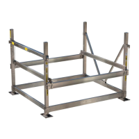
The resetable circuit breakers are designed to
trip if there is a short in the wires. The DC version
has one reset for the radio remote receiver and
the optional ood lights.
The AC version has two
resets, one for the radio
remote receiver and op-
tional ood lights and the
other reset is for the drive
motor. If one trips you can
reset it by pressing in the
reset button (Fig.5). If it
contiously trips refer to
the trouble shooting sec-
tion of this book.
Black Wire
Limit Switch
Yellow Wire
Wireless
Receiver
Blue Wire
Wired Remote
Fig 5
Reset
Advanced Switch Control (ASC) 24 volt DC
powered unit (above).