17
4.4 Wiring Diagrams
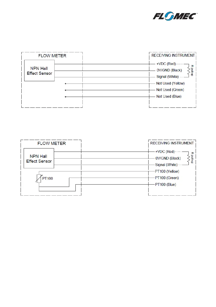
4.4.1 Standard Pulse Output Board
*A Pull-Up Resistor must be installed between the signal and +VDC connections
on the receiving instrument – unless the instrument has an integral pull-up*
4.4.2 Fuel Consumption Option
*A Pull-Up Resistor must be installed between the signal and +VDC connections
on the receiving instrument – unless the instrument has an integral pull-up*
*For installations using 2-wire RTD/PT100 connections, use only the yellow +
green wires.