INSTALLATION, OPERATION, &
MAINTENANCE MANUAL
TITLE: F7000 / 8000 Series Rev. V
Pilot-Operated Safety Relief Valve Page 20 of 41
25) Assemble the pressure adjustment (PA) screw and lock nut into the top of the bonnet.
26) Attach the cap to the PA screw, but do not tighten.
27) Install vent / bug screen into bonnet, ensuring that the male NPT end does not contact the spring.
Install the inlet screen into the body.
28) Mount the face seals onto the external mounting face of the body.
29) The pilot valve is now completely assembled and ready to be set per Section 5.0.
30) If applicable, install lockwire and lead seal between PA screw cap, bonnet, and proportional band
screw. Repair tag may be attached to wire.
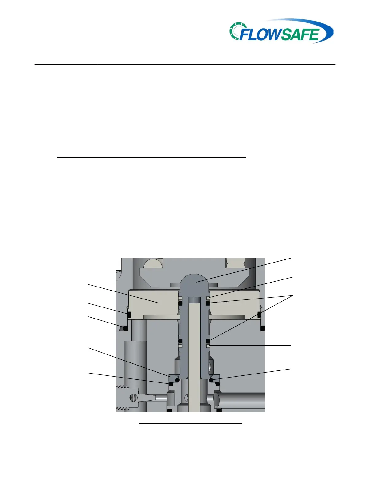
4.4 F300 PILOT VALVE, PISTON-STYLE (501 to 6000 psig) (See Illustrations below and on
Page 21)
A. F300 (Piston-style) Disassembly
CAUTION: It is extremely dangerous to attempt to disassemble any valve while it remains in
service with incoming line pressure.
1) Remove the pilot valve from the main valve, or safely block the incoming pressure before
disassembling the valve and performing maintenance.
2) Unscrew the pressure adjustment (PA) screw cap from the PA screw. Loosen the lock nut.
3) Loosen, but do not remove the PA screw from the bonnet.
4) Further disassembly can proceed in the reverse order from the assembly instructions on Page 22.
5) Replacement soft goods are listed in Section 8.0 of this manual.
See Section A-A on Page 18 for Backflow Preventer (BFP) details
UPPER
UPPER PISTON
BACKUP
RING
ADAPTER
BACKUP
RING
ADAPTER SEAL
SUPPORT
RING SEAL
SEAT RETAINER
NOZZLE
SLEEVE SEAL
F300 PILOT VALVE, HP PISTON-STYLE
(501 - 6,000 PSIG)
SEE FULL ASSEMBLY ON PAGE 22
 Loading...