INSTALLATION, OPERATION, &
MAINTENANCE MANUAL
TITLE: F7000 / 8000 Series Rev. V
Pilot-Operated Safety Relief Valve Page 6 of 41
2.2 SERVICE ENVELOPE
1
Confirm low-temperature applications with factory. Some O-ring seated valve configurations
have had cryogenic qualification testing performed down to -261°F (-163°C).
2
Pilot valve MAWP’s: 740 psig (F100); 6000 psig (F200, F300, & F500)
2.3 STORAGE AND HANDLING
A. STORAGE
Prior to installation, Flow Safe pressure relief valve assemblies and parts should be stored in a clean, dry
environment if possible. Inlet and outlet connections should remain covered until the item is ready for
installation.
For outside storage, protection from the elements is recommended particularly if plugs and flange covers are
not weather-tight. Exposed carbon steel surfaces should remain coated with a suitable rust inhibitor until the
assembly is ready for installation.
Even though elastomers and lubricants in the relief valve typically have a long shelf life and can be used in
environments down to -40
o
F/
o
C, operability of the main piston should be checked before placing the valve in
service after extended storage. See Section 2.4.
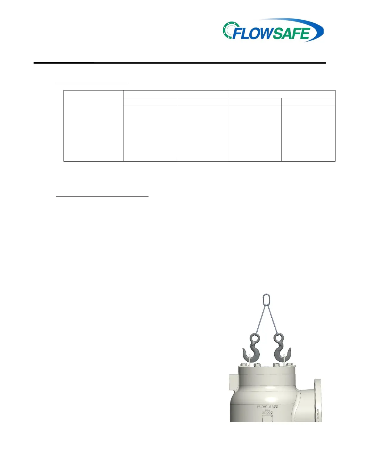
B. HANDLING AND LIFTING
Flange facings and other gasket sealing surfaces
shall be isolated from contact with other hard
objects through the use of cardboard or other soft
materials. Placing flanged surfaces directly on
wooden skids should be avoided due to possible
contact with nails.
Valve assemblies shall be lifted only from installed
lifting lugs or brackets, provided on all valves 2” x
3” and larger or with heavy flanges or accessories.
Smaller valves can be carried by hand (by holding
the main body and not tubing or other fittings).
When two lifting lugs are provided, generally on
valve assemblies 4” x 6” and larger, the load must
be balanced by use of a sling (chain, web, or
rope). See diagram below. All hooks, slings, and
other lifting devices shall be rated for the valve
assembly weight as identified by project drawings,
shipping documents, or scales used at receiving.
o
o
SET PRESSURE, psig (barg)
1
2
-30 (-34) 275 (135) 15 (1) 6000 (413)
® -30 (-34) 400 (204) 15 (1) 6000 (413)
-65 (-54) 225 (107) 15 (1) 6000 (413)
-65 (-54) 325 (163) 15 (1) 6000 (413)
® -423 (-252) 400 (204) 15 (1) 1000 (69)
Kel-F
-423 (-252)
0 (-18)
400 (204)
525 (273)
1000 (69)
3000 (207)
3000 (207)
6000 (413)
® -423 (-252) 500 (260) 3000 (207) 6000 (413)
TYPICAL LIFTING ARRANGEMENT
LIFTING BRACKETS
ROTATED 60-90°IN THIS VIEW

 Loading...