INSTALLATION, OPERATION, &
MAINTENANCE MANUAL
TITLE: F7000 / 8000 Series Rev. V
Pilot-Operated Safety Relief Valve Page 18 of 41
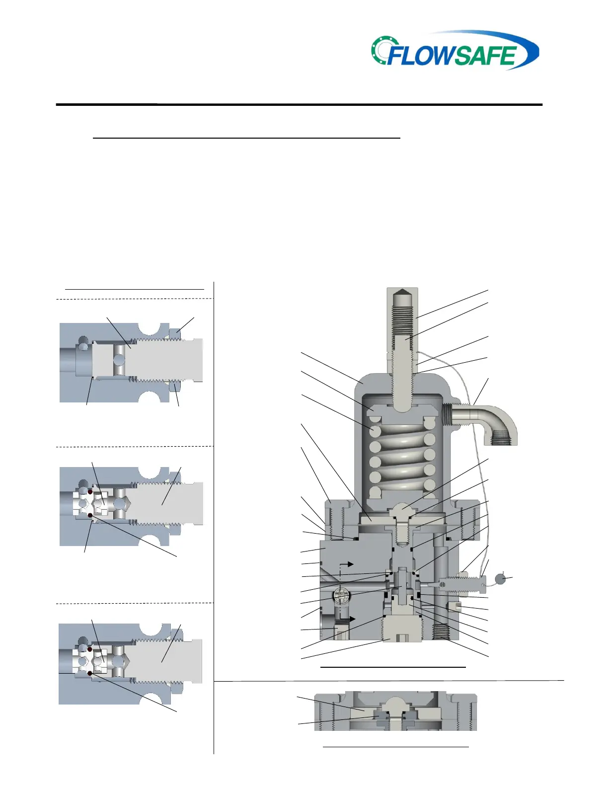
4.3 F300 PILOT VALVE, DIAPHRAGM-STYLE (15-500 psig) (See Illustration below)
A. F300 (Diaphragm-style) Disassembly
CAUTION: It is extremely dangerous to attempt to disassemble any valve while it remains in
service with incoming line pressure.
1) Remove the pilot valve from the main valve, or safely block the incoming pressure before
disassembling the valve and performing maintenance.
2) Unscrew the pressure adjustment (PA) screw cap from the PA screw. Loosen the lock nut.
3) Loosen, but do not remove the PA screw from the bonnet.
4) Further disassembly can proceed in the reverse order from the assembly instructions on Page 19.
5) Replacement soft goods are listed in Section 8.0 of this manual.
LOCK NUT
VENT /
BUG SCREEN
DIAPHRAGM
FASTENER
SPRING
WASHER
UPPER PISTON SEAL
SPRING
PRESSURE
ADJUSTMENT (PA)
PA CAP
BONNET
LOWER PISTON
DIAPHRAGM
SUPPORT DISC
DIAPHRAGM
INTERNAL PLUG
PLUG SEAL
INLET SCREEN
LOCK NUT / SEAL
PROPORTIONAL
SLEEVE
SEAT RETAINER
UPPER SLEEVE SEAL
UPPER PISTON
DIAPHRAGM
LOCKWIRE/
LEAD SEAL
DIAPHRAGM
PA SCREW SEAL
FACE SEAL
F300 PILOT VALVE, LP DIAPHRAGM-STYLE
(15 - 285 PSIG)
F300 PILOT VALVE, HP DIAPHRAGM-STYLE
(286 - 500 PSIG)
NEW DESIGN W/ O-RING (00-2313) SEAL
STANDARD DESIGN (LEGACY)
BACKFLOW PREVENTER (BFP) OPTIONS
BFP
PISTON
BFP
O-RING
BFP NOZZLE
O-RING SEAL
BFP NOZZLE,
BLANK
JAM
NUT
JAM NUT
SEAL
BFP
NOZZLE
DIAPHRAGM
DISC
DIAPHRAGM
BFP NOZZLE
BFP
PISTON
BFP
O-RING
BFP
NOZZLE

 Loading...