Copyright Reserved, DONGYANG Corporation 7
Special Notice
♦ When the meter contains removable coverplates. Leave the coverplate installed unless
accessory modules specify removal. Don’t remove the coverplates when the meter is
powered, or electrical shock and explosion hazard can be caused.
Flange Connections
The flange follows GB/T 9119-2000 (ISO 7005-1) RF (Raised Face).
Note: flange can be customized following other criterias.
Use a gasket between the meter flange and mating flange. Determine the material of the gasket
based on the operating conditions and type of fluid.………………………………………….
Note: Do not over tighten the flange bolts. This may cause the gasket to be compressed into the
flow stream and may decrease the accuracy of the meter.
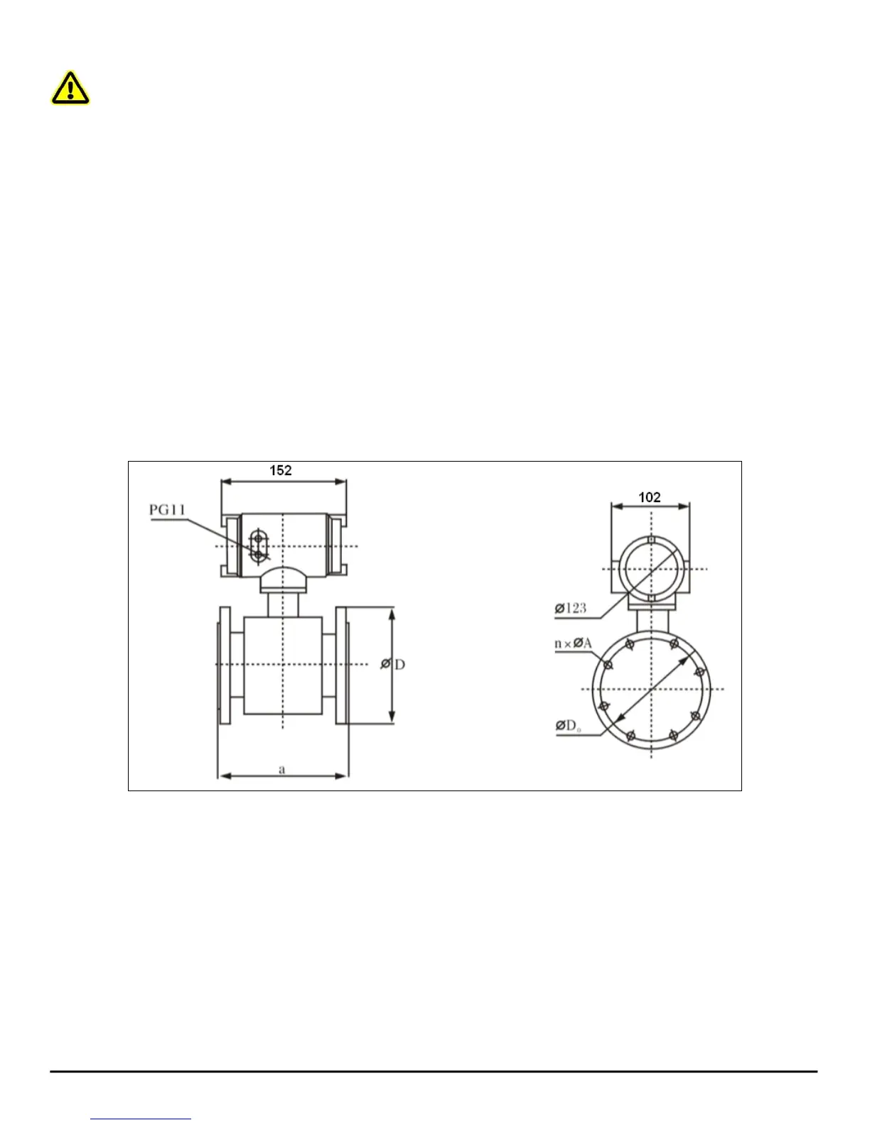
Installation Dimensions
See Figure 1 and Table 2 for detailed dimensions.
Figure 1: Drawings for Integrated/Remote Electromagnetic Flow Meter