FlowAct Diaphragm Linear Actuator FCD VLENIMFACTA4 10/16
70
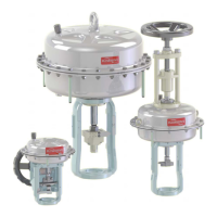
Actuator with attachments
Spring-to-open
WARNING
Danger of life in case of improper
disassembly. The maximum sum
of the spring preload can be 60 000 N !
Disassembly instruction of the actuator subas-
sembly
NOTICE
For the disassembly, special tools such as a
hydraulic spring press, stem wrench and stem
clamping tool are necessary. Limit disassembly only to neces-
sary components.
1. Fix the actuator on the assembly table, if this is not
already happened.
2. Disassemble the hexagon bolts (335), plain washers
(337) and hexagon nuts (351) from the casing (203).
3. Pull off the protection sleeve (339).
4. Lubricate the threats and disassemble the hexagon
bolts (336), plain washers (337) and hexagon nuts
(351) counterclockwise.
5. Lift off the diaphragm casing (202 - 389).
6. Fix the stem (211) with the stem clamping tool against
twisting.
WARNING
Risk of injury by jump-
ing out parts ! Pre-loaded
springs inside.
7. Loosen the stem (348) counterclockwise and remove
the lock washer (349), thrust washer (255), O-ring
(272), diaphragm (225), diaphragm plate (227), disk
(220), spacer bushing (228) and distance bushing
(374).
NOTICE
We recommend you to use a hy-
draulic spring press, as a minimum
requirement a beam and threaded rods in 8.8 quality
(ISO 898-1) or higher as well as washers and nuts al-
ternatively.
8. Remove the actuator springs (229), spring adjusting
plate (326) and distance plate (231).
9. Loosen the hexagon bolts (334) counterclockwise and
remove the O-rings (279), diaphragm casing (202)
and O-ring (276).
10. Disassemble the hexagon bolts (335), plain washers
(337) and hexagon nuts (351).
11. Pull off the protection sleeve (339).
WARNING
Risk of injury by jump-
ing out parts ! Pre-loaded
springs inside.
12. Lubricate the threads and loosen the long hexagon bolts
(336), plain washers (337) and hexagon nuts (351) uni-
formly in a clockwise sequence as the springs expand.
NOTICE
We recommend you to use a hydrau-
lic spring press, as a minimum re-
quirement a threaded rods in 8.8 quality (ISO 898-1)
or higher as well as washers and nuts alternatively.
13. Lift off the diaphragm casing (202 - 373).
14. Remove the stem clamping tool.
15. Disassemble the coupling parts (see page 54).
16. Carefully pull out the diaphragm-stem unit (211 - 380).
17. Remove the actuator springs (229), spring adjusting
plate (326) and distance plate (231).
18. Fix the diaphragm-stem unit into the stem clamping
tool.
19. Loosen the stem extension (380) with the stem wrench
counterclockwise and remove the lock washer (349),
thrust washer (255), O-ring (272), diaphragm (225),
diaphragm plate (227), disk (220), spacer bushing
(228) and distance bushing (374).
20. Pull out the scraper ring (273) and O-rings (275, 3x).
21. Check stressed surface areas for damage such as
scoring and deformities. Use a brass brush or similar
tool to clean bolting. Check for corrosion or any other
damage.