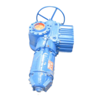
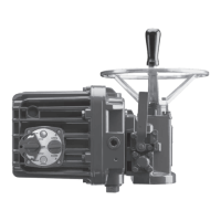
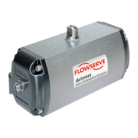
Do you have a question about the Flowserve NORBRO 40R Series and is the answer not in the manual?
Conduct a risk assessment and eliminate or reduce hazards to an acceptable level.
Work in accordance with Safe Systems of Work.
Wear all necessary Personal Protective Equipment.
Never remove or maintain an actuator unless de-pressurised, drained, and purged of media. Ensure no trapped pressure exists.
Never handle actuators used on harmful substances unless fully decontaminated and certified safe.
Never use an actuator beyond its prescribed operating parameters. Consult Flowserve for details.
Never modify or alter actuators unless manufacturer consulted or recommended.
Be careful when removing actuator; stored failsafe spring torque can cause unexpected operation and injury.
Each actuator has identification information on the product label attached to the body.
Ball valves can trap media. Ensure no pressure before removing bolts or valve from line.
Double-acting: 2-8 bar. Spring-return: 2.5-7 bar. Spring-return can use 2.5-5.5 bar with fewer springs.
Describes 90° rotation via pistons, overtravel, and spring-return mechanism.
Describes how solenoid controls air supply to center or end chambers for double-acting and spring-return.
In case of air failure, use a wrench on the top shaft to cycle the actuator manually.
Actuator must be isolated pneumatically and electrically before any maintenance activity.
Warning: Consult rebuilding instructions before disassembling the actuator for any reason.
Checks for valve freedom, correct actuator size, speed control screws, voltage, and air supply.
Check solenoid for clicking sound. If no sound, check plunger retraction after applying voltage.
Diagnose leakage by checking voltage and air supply. Low voltage or pressure drops can cause issues.
Disconnect air/electrical service. Remove actuator and mounting bracket from valve.
Remove end cap screws, end caps, bearings, and O-rings. Handle top-hat bearings carefully.
Warning: Spring-return actuators contain energized springs. Follow section carefully for safe disassembly.
Loosen end cap screws in sequence to relieve spring preload. Use caution on larger actuators.
Remove position indicator, shaft clip, and washer to extract shaft through the bottom opening.
Align shaft teeth with piston rack teeth for proper 90° rotation. Ensure correct tooth meshing.
Push pistons into body and turn shaft clockwise. Ensure pistons move towards center upon engagement.
Replace springs in their identical original positions in the end cap.
If a spring fails, replace all springs in the actuator and any other damaged parts.
Engage end cap screws and uniformly tighten to load springs, preventing buckling.
| Brand | Flowserve |
|---|---|
| Model | NORBRO 40R Series |
| Category | Controller |
| Language | English |

