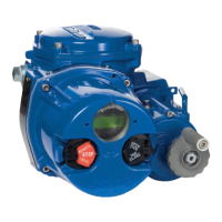
Foolproof pin
location holes
Blank support rod
(without cross hole)
Inlet support rod
(with cross hole)
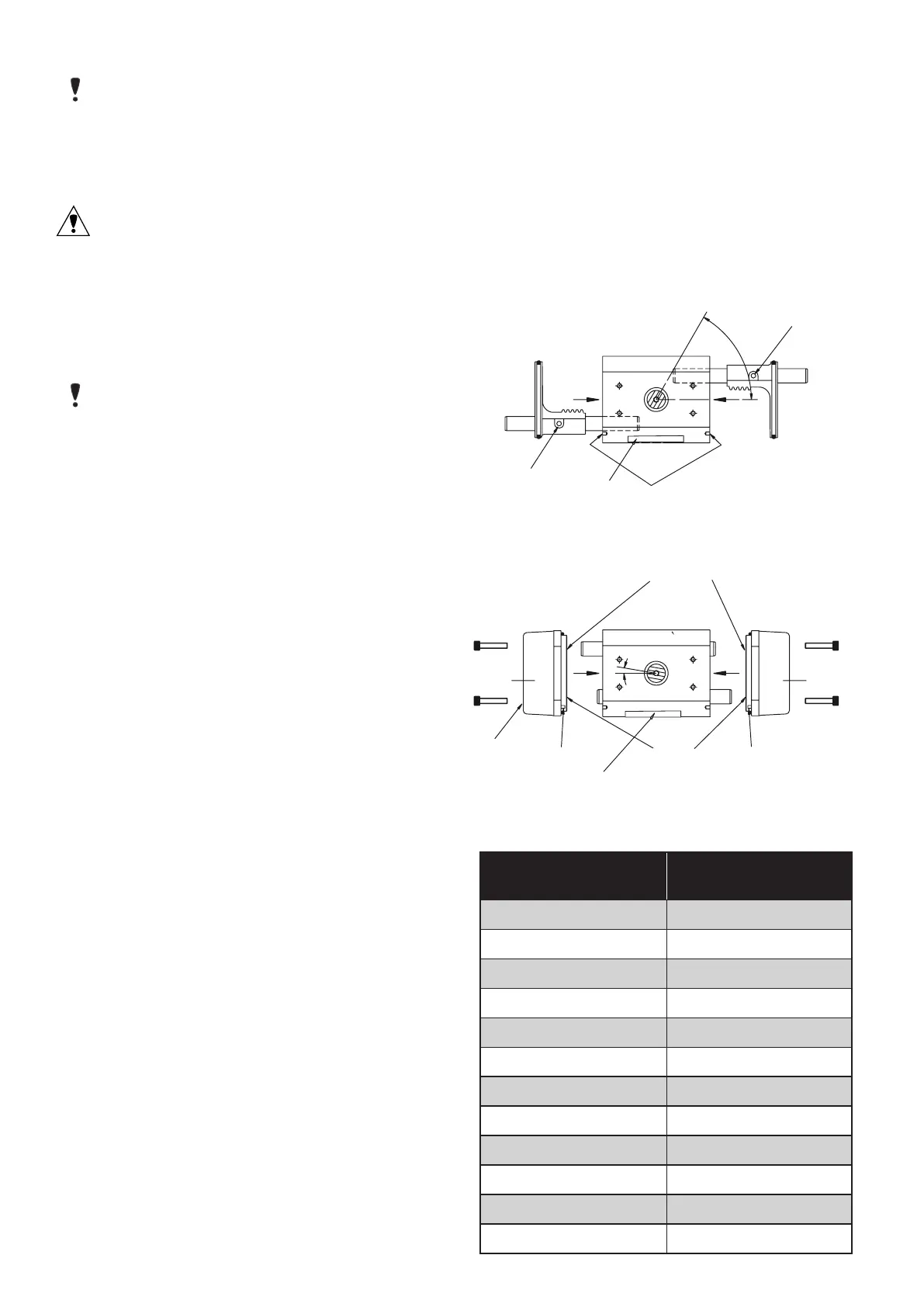
Label
Position of pinion
flats and groove
(60º approx.)
Bores containing
bearings only
Bores containing
bearings and
0-rings
Foolproof pin
Foolproof pin
Inlet
End Cap End Cap
Inlet port
Label
#
Limit Stop
Actuator
Size
Pinion Offset Angle #
05 0°
10 10°
15 2°
20 2°
25 2°
30 2°
33 2°
35 2°
40 0°
42 0°
45 0°
50 12°
NOTE:
Size 40R, if furnished with factory sole-
noid, shall be “cross-line” mounted (i.e. at 90
degrees to the pipe run) to ensure adequate
clearance for air connections.
5.5 Prepare valve for actuation:
CAUTION: Ball valves can trap pressurized
media in the cavity. If it is necessary to remove
any valve body bolts, stem nuts, or remove
valve from the line, and if the valve is or has
been in operation, make sure there is NO pres-
sure to or in the valve and operate valve one
full cycle.
NOTE:
It is not normally necessary to remove
any valve body bolts or remove valve from line
in order to mount actuator.
5.5.1 Rotate valve ball and stem to position neces-
sary to achieve desired operation.
5.6 Attach bracket/actuator assembly to valve as
follows:
5.6.1 Center coupling on valve stem.
5.6.2 Lower mounting bracket/actuator assembly
over coupling and onto valve, making sure that
female star drive or NORBRO square actuator
shaft engages in the correct orientation with
the coupling.
5.6.3 Secure bracket to valve using cap screws and
lockwashers, or bolts and nuts provided in
mounting kit. Tighten securely.
5.6.4 Install set screws (if any) in coupling and
tighten securely.
5.6.5 Determine if mode of operation (air to open or
close/fail open or closed) is as desired; if not:
Air to Open or Close - On all sizes of 40R
double-acting and spring-return actuators,
the female drive shaft is either a NORBRO
square or a star drive This allows selection
of either mode of operation by indexing the
coupling (including valve ball and stem)
90° to the actuator shaft, while keeping the
actuator in an in-line orientation.
Fail Open or Fail Close - The normal method
of mounting is to have the actuator in line
with the pipe line and the valve and actuator
in the “FAIL-CLOSED” (Clockwise to close)
position. “FAIL-OPEN” can be achieved using
the method above but the actuator will then
work as Clockwise to open).
FOR“FAIL-OPEN” but with Clockwise to close
operation, the pistons in the actuator will
need to be removed and reasembled from
the opposite ends of the actuator (keeping
the guide rods the same sidesrelative to the
body). This will result in a slight offset of
pinion position on some sizes. See following:

 Loading...