7.4 Recommended Tubing Sizes:
In order to provide sufficient flow of supply
air to the Series 40R actuator, the following
tubing sizes are recommended:
Actuator Size
Runs Up To
1.5 m Long
Runs Over
1.5 m Long
05, 10, 15, 20, 25
1
/
8
¼
30, 33, 35, 40, 42,
45
¼
3
/
8
50 ¼ ½
8 AIR CONSUMPTION
The following chart shows the amount of
pressurized (5 bar) air consumed per stroke
in litres. To determine the total amount of air
consumed per complete cycle for double-
acting actuators, simply add the volumes for
both the opening and closing strokes together;
for spring return units, the total volume of
air consumed is the volume shown for the
opening stroke.
9
INSTALLATION ACCESSORIES
For details of installation of accessories refer
to the installation instructions contained in
respective accessory kit.
10 OPERATION
10.1 Basic Actuator
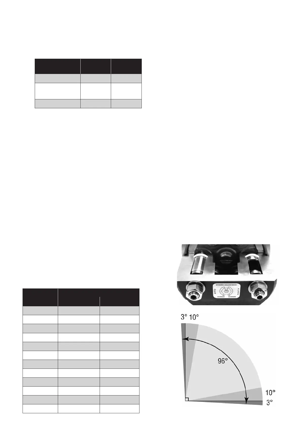
The Series 40R actuator drive shaft rotates
through a full 90° segment with approximately
3° overtravel at each end of travel (limit stop
version). Rotation is accomplished by feeding
supply air into the center chamber, forcing
the two opposing pistons apart, resulting in
a counter-clockwise rotation of the drive shaft
to the “open” position. For double-acting actu-
ators, closure is obtained by feeding supply
air into the end cap chambers, which forces
the pistons together, resulting in a clockwise
rotation of the drive pinion. For spring-return
actuators, closure is accomplished by means
of springs contained within the end caps which
force the pistons together when the supply air
to the center chamber has been interrupted.
If rotation opposite to that described above is
required, refer to the section on Installation for
the proper procedure to reverse the rotation.
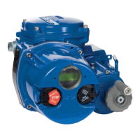
The accurate rotation of the actuator pinion
is controlled through the adjustment of two
hexagon headed bolts on the end cap. Each
bolt will control either the open or closing
stroke (based on how the actuator has been
orientated on the valve). The adjustment of
each bolt is shown on the end cap. Actuators
are factory set to provide a 90˚ operation. If
adjustment needs to be made the lock nut
will need to be backed off, the adjustment
screw rotated to provide correct positioning
Actuator
Size
Air consumption litres
Opening Stroke Closing Stroke
05 0.05 0.05
10 0.17 0.22
15 0.35 0.39
20 0.69 0.74
25 1.22 1.31
30 1.86 2.05
33 3.39 4.79
35 3.93 5.54
40 7.73 8.19
42 12.0 13.89
45 13.51 20.0
50 23.87 30.5

 Loading...