Series 40R Sizes 10 - 42
4.5 bar - 8 springs - 4 per end cap. Remove center spring.
4.0 bar - 8 springs - 4 per end cap. Remove center spring.
3.5 bar - 6 springs - 3 per end cap. Use three on a diagonal.
3.0 bar - 4 springs - 2 per end cap. Use two in opposite corners.
Series 40 Sizes 45 - 50
4.5 bar - 20 springs - 10 per end cap.
Remove required number of
springs starting in the center.
Remaining springs should be
evenly spaced as possible.
4.0 bar - 20 springs - 10 per end cap.
3.5 bar - 16 springs - 8 per end cap.
3.0 bar - 12 springs - 6 per end cap.
The size 05 spring-return actuator operating at 5.5 bar has four
springs (two per end cap). For air supplies of 4.5, 4.0 or 3.0, remove
inner spring of each end cap.
14.2.11
Install O-Ring (15A) into and replace the
actuator end caps, (5 or 5A and 5B), noting
that the “foolproof” pin between the body and
end cap mates properly (10–50 sizes only).
NOTE: For spring return actuators, see
spring installation section on page 13 before
installing end caps.
NOTE: When installing the end cap O-Rings,
use a small amount of a general purpose lubri-
cant, such as petroleum jelly, to hold them in
place for ease of assembly and to avoid having
them drop down and get pinched.
On Rev. R2 and earlier actuators, be sure
O-Ring is installed in groove on end cap.
14.2.12
Replace position indicator (17). See Section 6.
15 SPRING-RETURN ACTUATOR
15.1 When replacing springs in a spring-return
actuator, ensure that the springs are replaced
in their identical position in the end cap from
where they were removed.
IMPORTANT: When less than the standard
number of springs are used in each end cap,
these springs should be positioned according
to the air supply figures below.
The values listed below are for standard and
less than the standard air pressure as required
per the ordering code.
NOTE: Maximum operating pressure does not
change.
15.2 If a spring-return actuator is being repaired
due to a failed spring, REPLACE all the springs
in this actuator, as well as any other parts
which may have been damaged.
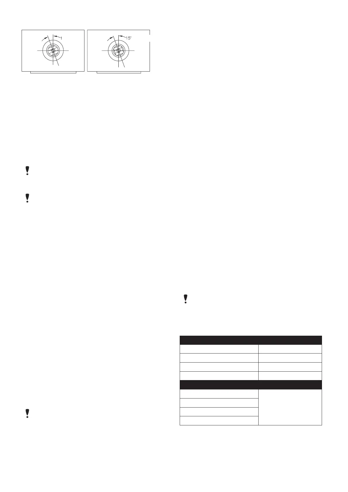
Size 05 - 20 Size 25 - 50
15˚ - 20˚
15˚ - 20˚
Figure 2
Alignment of Shaft at Reassembly
IMPORTANT:
Align gear teeth on the shaft as per Figure 1.
15.3 When replacing the springs in a spring-re-
turn actuator, place the springs in the end
cap pocket after thoroughly lubricating each
spring. Be generous with lubricant!
15.4 With the springs pointing up and the end cap
on a solid surface, place the actuator body
over the springs and the proper end cap. (Each
end cap can only be mounted to just one end
of the actuator body, as there is a “foolproof”
pin in the end cap, which aligns with a hole in
the body).
15.5 Force the body down and begin by engaging
two end cap screws (5C) by hand through
the end cap. Take each end cap screw up in
SMALL and EQUAL turns. Once the end cap is
temporarily secured to the body, turn the actu-
ator over to its normal position and uniformly
take up the four end cap screws. Uniformly
load all the springs to prevent any spring from
buckling.
IMPORTANT: Locating nibs are cast into the
piston face on sizes 25 to 50. The actuator
springs must fit over these locating nibs on
the piston face. Care in following the above
instructions will ensure the proper alignment
of the spring in the actuator body — proper
contact with the piston face and end cap.
15.6 In a similar manner, as written in the previous
steps, replace the springs in the other end of
the actuator body.
NOTE: On sizes 40 to 50 limit stop, only
encapsulated springs (pre-compressed) can
be used with this design.

 Loading...