To order proper parts, please specify the actuator size, model and revision number. Use the standard nomencla-
ture listed above.
The rebuilding kits include Items 15A, 15C through 15G, 10, 19 and stainless steel washer. Color of some
replacement parts, such as bearings, may vary from the parts removed.
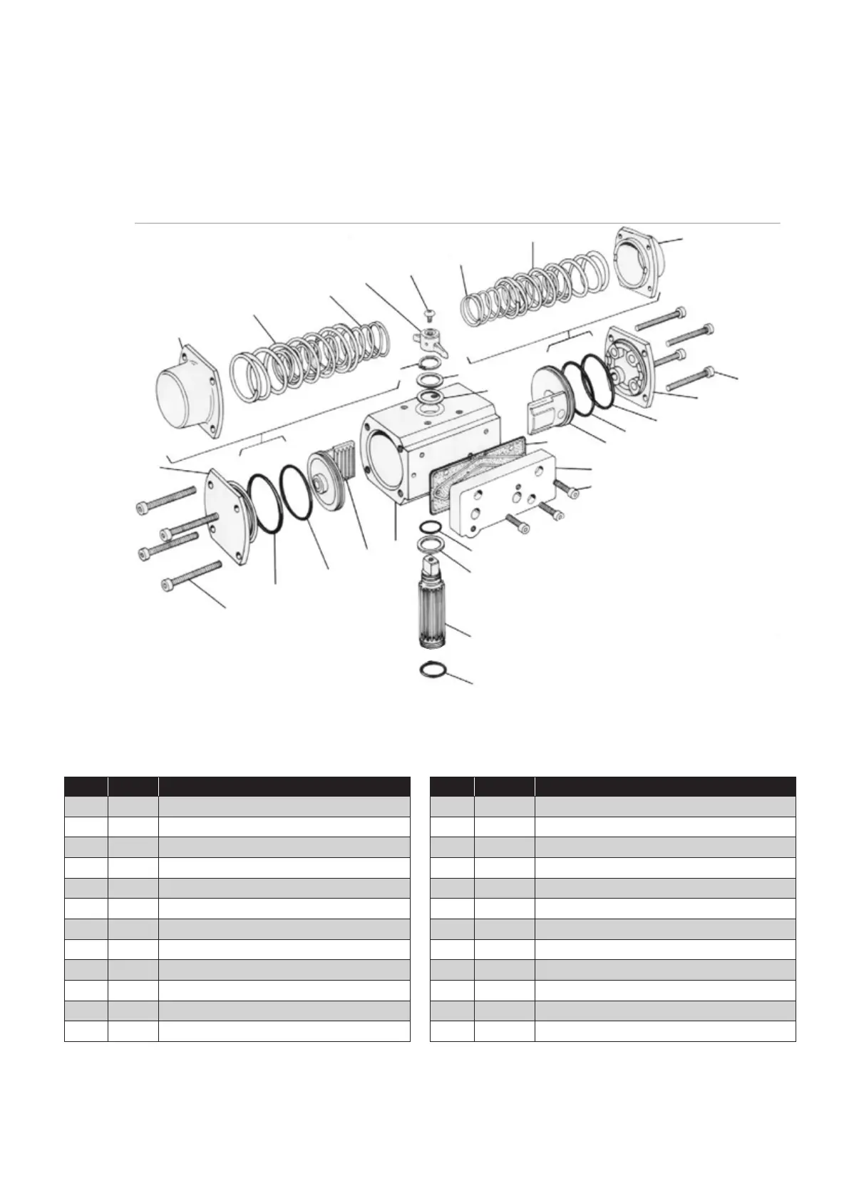
16 Size 05 Exploded view/parts/materials
Item Qty. Description Item Qty. Description
1 1 Body 14A 2 Inner Springs (See Table Page 13)
2 1 Shaft 14B 2 Outer Springs (See Table Page 13)
3 2 Pistons 15A 2 End Cap O-Rings
4 2 Guide Rods 15C 2 Piston O-Rings
5 2 End Caps 15D 1 Top Shaft O-Ring
5A 1 Solenoid Block (Inlet) End Cap 15F 1 Shaft Clip
5B 1 Limit Switch End Cap 15G 1 Top Pinion Bearing
5C 8 End Cap Screws (Metric) 17 1 Position Indicator
10 1 Thrust Bearing 18 1 Indicator Mounting Screw
11 1 Nameplate (Not Shown) 19 1 Interface Gasket
12 2 Piston Set Screws 20 1 Solenoid Block Interface Plate
13 2 Pipe Plugs 21 3 Plate Mounting Screws (Metric)
5C
8E
8D
14B
14A
17
18
14A
14A
15F
S. S. Washer
15G
5
(Double acting)
15A
15C
3
19
20
21
5C
15A
15C
3
1
15D
10
2
15E
7A
8E
8B
18C
5
(Spring return)
5
(Spring return)
5
(Double acting)

 Loading...