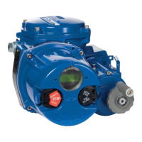
13.2.4 If control block and solenoid are operating
correctly, proceed to Section 13.3.2 below.
13.3 If the actuator functions but exhibits leakage,
or power loss accompanied by leakage,
proceed as follows:
13.3 .1 Check voltage. Voltage must be within 10% of
the specified voltage (low voltage will cause
leakage out of the back of the solenoid and
burn out the coil).
13.3.2 Check air supply. Be certain that no sharp air
pressure drops occur as unit is cycled. Loss
of air pressure can cause incomplete shifting
of the spool valves used in all double-acting
units, which results in bypass leakage and
substantial actuator torque losses.
13.4 If air supply and voltage are adequate, proceed
as follows:
13.4.1 If leak is at solenoid exhaust port, replace the
solenoid.
13.4.2 If leak occurs at exhaust ports in the block
itself, the trouble will be in either the spool
valves in the block, or at one of the piston
seals of the actuator. A leaking piston seal will
usually leak on either cycle.
On spring-return actuators, piston seal leakage
will show at the breather port of the end cap, or
for 05 size, the solenoid block interface plate.
The recommended procedure in the cases
above is to replace the spool valve O-rings. If
the leakage persists, rebuild the actuator using
a factory-supplied repair kit.
13.5 For actuators without the solenoid control
block, or if block and solenoid are operating
correctly, remove the actuator from the valve,
disassemble (per Rebuilding Instructions) and
check the following:
13.5.1 Make sure that all internal porting is free and
clear of any obstructions. End caps, guide rods
and pistons are air transporting components.
NOTE: The most common problem encoun-
tered on 40R actuators is the improper
replacement of the piston guide rod assembly
with the hole in it, relative to the nameplate on
the body (see section 14.2.7 on page 12).
13.5.2 Make certain that the actuator has lubrication,
and that there is no solidified grease between
the pinion and the piston racks:
• If actuator has no lubriction, apply generous
amountof grease. If actuator is prepared for
high or low temperature operation, consult
Flowserve for proper lubricants.
• If solidified grease betweenthe pinion and the
piston racks is present, clean, dry, re-grease
and reassemble.
13.5.3 Verify that actuator pinion shaft and/or
pistons are not bound. If bound, reassemble
per Rebuilding Instructions.
13.5.4 If unit exhibits excessive amounts of backlash,
check teeth on piston racks for wear. If worn,
replace piston assemblies.
13.5.5 In spring-return actuators, check for
misplaced or broken springs. If springs are
broken, check body bore for scoring:
• If springs are broken, replace springs.
SPRINGS SHOULD ALWAYS BE REPLACED
IN COMPLETE SETS.
• If body bore is scored,replace it. Also, replace
piston O rings (contained in repair kit).
13.5.6 If actuator is free, valve is free and control
block (if used) is shifting air properly, reas-
semble the actuator and retest. If unit still fails
to operate, consult Flowserve.
14 REBUILDING INSTRUCTIONS
NOTE: For identification of all numbered parts
discussed below, consult exploded view of
actuator (see pages 14/15)
After actuator has been repaired, mark rebuild
label accordingly and apply to actuator.
14.1 Actuator disassembly
14.1.1 Disconnect the air supply and electrical service
to the actuator.
14.1.2 Remove the actuator and its mounting bracket
from the valve. If the actuator uses a posi-
tioner, loosen the set screws in the coupling
between the valve and actuator. (See Caution
note below.)
CAUTION: Ball valves can trap pressur-
ized media in the cavity. Isolate the piping
system in which the actuator/valve assembly
is mounted and relieve any pressure on the
valve. To remove the actuator bracket from
a three-piece non-top-mount style valve, the
two top valve body bolts must be removed.
14.1.3 Remove the actuator bracket (and actuator
positioner) from the actuator to begin repair.
(Note mounting of removed bracket and posi-
tioner for easy reassembly.)
14.1.4 It is not necessary to remove solenoid control
block (if so equipped) to rebuild actuator.
However, if it becomes necessary to remove
the block, begin by removing the solenoid
block bolts. Use care to retain the solenoid
block gasket.
For 05 size only, also remove the solenoid
block interface plate (20) and the interface
gasket (19) by removing the three screws
(21).

 Loading...