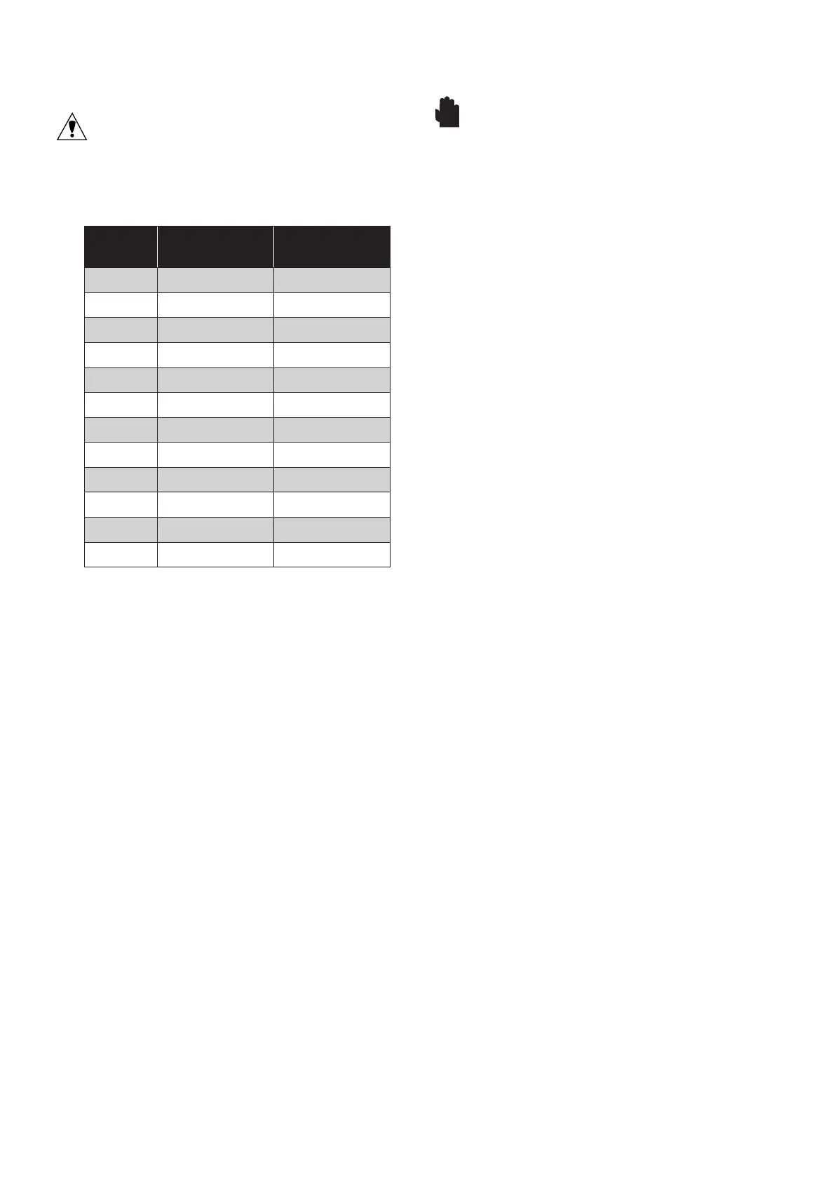
Actuator
size
Fastener size Torque
05 M5 4Nm
10 M6 9Nm
15 M6 9Nm
20 M8 19Nm
25 M8 19Nm
30 M10 35Nm
33 M10 35Nm
35 M12 49Nm
40 M12 49Nm
42 M16 98Nm
45 M16 98Nm
45 M20 216Nm
11 MAINTENANCE
CAUTION: The actuator must be isolated
both pneumatically and electrically before any
maintenance activity is begun.
Periodic checks should be performed to make
certain that all fasteners remain tight.
All actuators are supplied with sufficient lubri-
cation for their normal working life. If required,
recommended lubrication for all standard
actuators is a Rocol Sapphire Lo-Temp 2
grease. Consult Flowserve for lubricants used
for high or low temperature applications.
Depending upon the conditions under which
the actuator must work, such as extended duty,
non-compatible operating media or abnormal
operating conditions, periodic replacement
of internal seals is recommended. Repair kits
containing all necessary seals can be obtained
through any authorized Flowserve distributor.
On spring-return actuators, the springs may
need replacement after extended duty since
springs may fatigue and break. SPRINGS
SHOULD ALWAYS BE REPLACED IN
COMPLETE SETS.
12
SPARE PARTS
The following are recommended spare parts
which should be kept on hand for Series 40R
pneumatic actuators:
Repair Kit(s) – Kits contain all necessary seals,
bearings and instructions.
13
TROUBLESHOOTING
WARNING:
BEFORE DISASSEMBLING
ACTUATOR FOR ANY REASON, CONSULT
REBUILDING INSTRUCTIONS CONTAINED IN
FOLLOWING SECTION.
For solenoid controlled actuators:
13.1 If actuator does not function, check to ascer-
tain:
13.1.1 That valve is free to rotate.
13.1.2 That actuator is the correct size.
13.1 3 Any speed control screws are loose (if screws
are tightened all the way, actuator will not
operate).
13.1.4 That correct voltage is supplied to solenoid.
13.1.5 That sufficient air supply is available at inlet to
control block. Inlet pressure to control block
should be at least 2.5 bar for double-acting, 5
bar for spring-return (unless a reduced spring
complement is installed (fewer springs)).
When checking supply pressure, place gauge
in line at control block inlet and monitor gauge
for unexpected pressure drops.
13.2 If proper voltage and air pressure have been
verified and valve is free, proceed as follows:
13.2.1 Turn on signal voltage. Check solenoid for
clicking sound.
13.2.2 If no sound is detected, remove air pressure
and turn off signal voltage.
• Carefully unscrew solenoid and solenoid
stem from block.
• Reapply signal voltage and observe solnoid
plunger. If it does not retract, replace solenoid.
13.2.3 If solenoid functions, remove solenoid valve
block and place on bench. Connect to reduced
air supply (4 bar) and correct voltage. Switch
signal voltage and check air flow. Air should
flow out only one output port when solenoid
is energized. The flow should occur only at the
other port when de-energized. (Slight back
pressure may be required to shift the valve
spool. This may be generated by obstructing
the outlet ports.)

 Loading...