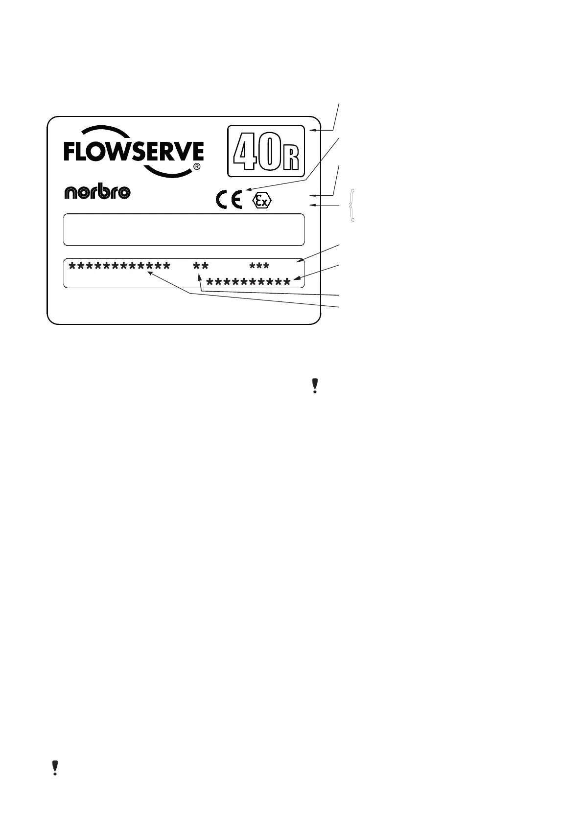
4 ACTUATOR MARKINGS
Each actuator has the following identification infor-
mation on the product label attached to the side of
the body:
ATEX Directive: If the product label carries the ATEX
Directive number '94/9/EC' followed by the Explo-
sion Protection Symbol and codes identifying the
equipment group and category, the zone suitability
and protection type beside the CE mark, the product
complies with the ATEX Directive and The Equipment
and Protective Systems Intended for Use in Poten-
tially Explosive Atmospheres Regulations 1996.
Definition of product label marking above:
'II' = Equipment Group.
'2' = Equipment Category.
'G' = Gas Zone suitability (Zones 1 & 2).
'D' = Dust Zone suitability (Zones 21 & 22).
'c' = type of protection i.e. constructional safety (prEN
13463-5).
'X' = Special temperature reference (Surface
Temperature: As per BS EN 13463-1:2001 paragraph
14.2g, the temperature class or maximum surface
temperature cannot be marked on the product as it is
dependent on the operating conditions).
The operational temperature range is as follows:
(S) = Standard -20 °C to +100 °C.
(L) = Low Temperature variant -40 °C to +85 °C.
(H) = High Temperature variant -20 °C to +150 °C.
NOTE:
Under constant use the surface tempera-
ture of expose parts may rise by a maximum
20 °C above the operating media temperature.
5 INSTALLATION
NOTE:
The Series 40R actuator is normally
installed with its major axis parallel to the
pipe line. The actuator can be oriented above,
beside or beneath the valve without affecting
its operation.
Sizes 10-35 actuators may come with an ISO
locating ring, used for optional ISO mounting.
Size 40-50 actuators have an integral ISO
location ring.
5.1 Determine mode of operation desired
(normally open or normally closed) of the
valve.
5.2 Determine desired quadrant for bracket
attachment and direction of mounting of actu-
ator (in-line or cross-line).
5.3 Attach mounting bracket to actuator using four
(4) cap screws and lock washers provided in
mounting kit. To avoid any damage to the
Series 40R actuator body, ONLY the proper
length screws supplied with the mounting kit
should be used.
5.4 If an ISO locating ring is used, insert ISO
locating ring into groove on bottom of actu-
ator before attaching to bracket. Ring can
be permanently held in groove by applying
Loctite
®
638 to ring before inserting in groove.
Maximum Working Pressure
Works Order Number
Year of Manufacture
Atex Directive
Product Series
Explosion Protection Symbol,
Equipment Group & Category,
Zone Suitability and Protection Type
CE Mark
Flowserve Flow Control (UK) Ltd
Product Code
Website: www.flowserve.com UK & Foreign Patents
IMPORTANT: Dismantle only in accordance with Installation,
Operation & Maintenance notes. Refer to notes to ensure proper
use of actuator. Maximum Working Pressure see below.
WORKS ORDER
II2GDcX
94/9/EC
Flowserve Flow Control (UK) Ltd.
Tel: +44(0)1444 314400 Fax: +44(0)1444 314401
PRODUCT CODE
PNEUMATIC ACTUATOR
YEAR
{
BAR

 Loading...