and the lock nut retightened. For size 10 to
35 turn screw clockwise to decrease rotation
and counterclockwise to increase rotation. For
size 40 to 50 the reverse applies. It is critical
to retighten to ensure an effective seal of the
washer.
Care should be taken to secure travel stop
setting when tightening lock nut.
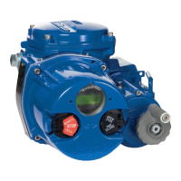
10.2 Actuator With Solenoid
Double-Acting – Air is supplied to the one
BSPP port on the bottom of the block. When
the solenoid is energized, the spring-loaded
plunger is withdrawn, allowing the supply
air to shift the spool within the block, which
opens the supply path to the center chamber
of the actuator. Air from the end chambers of
the actuator is allowed to pass through the
block and exhaust to atmosphere.
When the solenoid is de-energized, the spring-
loaded plunger blocks the flow of air to the
center chamber of the actuator. The supply air
now shifts the spool within the block to a posi-
tion which opens the supply path to the end
chambers of the actuator. Air from the center
chamber of the actuator is allowed to pass
through the block and exhaust to atmosphere.
The double-acting solenoid assembly is elec-
trically fail-safe. That is, it will return to its
de-energized position upon electrical failure
and cycle the actuator to the closed position
provided the air supply is not interrupted.
Spring-Return – Air is supplied to the one
BSPP port on the bottom of the block. When
the solenoid is energized, the spring-loaded
plunger is withdrawn, which opens the supply
path to the center chamber of the actuator.
Air from the end chambers of the actuator is
allowed to pass directly through the block and
exhaust to atmosphere.
When the solenoid is de-energized, the
spring-loaded plunger blocks the flow of air
to the center chamber of the actuator. The
springs in the end cap of the actuator, which
were compressed on the opening stroke, now
relax, forcing the air contained in the center
chamber of the actuator to exhaust through its
supply port in the solenoid block. The exhaust
air passes through the block and the solenoid
where it exhausts to atmosphere.
10.3 Standard Stroke Times
Standard stroke times of the Series 40R actu-
ator are shown in the following table. Times
shown are in seconds and represent average
times under 50% load conditions with an air
supply pressure of 5 bar. Times shown are
per stroke for double acting actuators. For
spring-return actuators, the opening stroke
times may be slightly longer; stroke times
for the closing (spring) stroke are dependent
upon the number of springs used.
The figures shown below are meant as an
indication of obtainable speeds only. Faster or
slower speeds are obtainable, if required, by
using additional control equipment.
Actuator Size Stroke Time (sec.)
05 1
10 1
15 1
20 1
25 2–3
30 3–4
33 4–5
35 4–5
40 5–6
42 6–7
45 10–12
50 12–14
10.4. Manual Operation
In the event of air failure, the Series 40R
actuator can be cycled manually. This is
accomplished by applying a wrench to the
exposed top shaft of the actuator and turning
it in the desired direction.
WARNING: Care must be taken to ensure that
the actuator is not operated automatically
while manual operation is being performed.

 Loading...