Replace the split-ring style bearing (6) and
guide rod O-ring(s) (15B) into I.D. groove(s)
in each piston (3). Install O-Rings (15C) onto
pistons.
For size 05 actuators, install O-rings (15C)
onto the pistons.
14.2.4 Replace O-ring (15E) and bearing (15H)
(10–42 sizes only) on the bottom of shaft. On
the top of the shaft add the two stainless steel
washers (10–35 sizes only) with the thrust
bearing (10) between them. NOTE: On later
models only a single stainless steel washer
is used and thrust bearing (10) is not used.
Locate the top bearing (15G) and O-ring (15D)
into the body. Insert the shaft through the
larger opening in the bottom of the body.
14.2.5 Replace the stainless steel washer over the
top shaft extension.
14.2.6 For sizes 10–50, very carefully align the piston
guide rod assemblies inside the body. Keep
the pistons square to the body. (This is very
important in the 30, 40R actuator where steel
set screws can cause internal body damage if
the piston assemblies “cock” inside the actu-
ator body).
IMPORTANT:
One piston guide rod assembly
has a through hole drilled in it. It can be easily
located by looking down the ends of both
guide rods. This piston assembly must be
reassembled, with its respective guide rod,
opposite the nameplate on the body, as it was
removed.
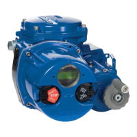
IMPORTANT: Note the relative location of the
shaft teeth and the piston assembly's rack
teeth. The above figure is viewed when looking
at the top of the actuator.
For size 05, align the pistons inside the body.
Keep the pistons square to the body.
VERY IMPORTANT: Install the NEW shaft clip
(15F) into its mating groove on the top shaft
extension. (The removed shaft clip is not to be
reused).
Place the numbered side up on the shaft clip
and be certain the clip is fully seated in its
groove. See Note at bottom of page 10 for
installation of spiral-ring type shaft clip (which
newer rebuilding kits will contain).
14.2.7 Align the shaft so that the teeth on the shaft
will “pick-up” the piston assembly’s rack teeth
when turning the
top extension of the shaft
clockwise (CW). (See Figure 1).
IMPORTANT: Proper 90° rotation can only
be ensured if the shaft teeth begin to mesh
with the piston assembly’s teeth at the “proper
tooth” between these meshing gear pairs.
(See Figure 1).
14.2.8 To ensure proper meshing of teeth, move
the shaft 15 to 20 degrees counter-clockwise
(CCW) from its normal position when the
piston assemblies are located at the body
ends. (See Figure 2.) NOTE: The “normal posi-
tion” of the shaft on the 05–20 sizes is when
the top flats are parallel to the main axis of the
actuator body. On the 25– 50 sizes the teeth of
the shaft will be on the left side of the actuator
when viewed from the ends of actuator. (See
Figure 1).
14.2.9
With the piston assemblies in the body, gently
push each piston into the body. Turn the top
shaft extension clockwise (CW). Do not allow
the pistons to “cock”.
At the proper point of engagement between
the shaft and piston assemblies, both piston
assemblies will move toward the center of the
body when turning the top shaft extension of
the actuator clockwise (CW).
14.2.10
Once the shaft and pistons are properly
engaged, ensure that smooth movement
and 90 degree operation can occur without
moving the pistons out of the actuator body.
This is important!
CAUTION: For sizes 40 to 50 limit stop variant,
the limit stop end cap must be assembled
first. Once assembled, feed the limit stop bolts
through the guide rods and screw into the end
cap. Add the sealing washer, backing washer
and lock nut and then attach the air inlet end
cap. This should be done in conjunction with
the instructions below.
Figure 1
Pistons at End of Body
°
Nameplate

 Loading...