FlowAct Diaphragm Linear Actuator FCD VLENIMFACTA4 10/16
9
flowserve.com
WARNING
Diaphragm linear actuators are pressure vessels.
Improper opening of the actuator can result in bodily injury.
Actuator assembly procedure
1. Fix the valve on the assembly table.
NOTICE
The orientation of the valve must be
in accordance with the appropriate
mounting position !
2. Lubricate all threads with a suitable, approved lubri-
cant (see Section 16).
3. Mount the actuator / yoke and yoke lock nut (76) onto
the valve bonnet.
4. Finger tighten and fix the yoke lock nut; turn clockwise
(see Section 15).
NOTICE
The legs of the yoke should be paral-
lel to the flow direction !
5. If the fail safe position at air failure moves the stem
into closing position then must the actuator connected
with the air supply to move the stem into the open
(retracted) position (in most cases).
WARNING
Due to risk of crushing
hazard, do not work be-
tween the yoke legs while the valve is in operation.
6. Mount the lock nut (113) and lower coupling (345)
onto the valve stem.
7. Justify the plug against the seat.
8. Adjust the distance between the lower coupling (345)
ant the upper coupling (249) with the aid of an adapter
in stroke height (Figure 7).
9. Disconnect the air supply so that the actuator moves
to the close position.
10. Mount the cap screws (240).
11. Lock the lock nut (113). Secure the upper coupling
(249) against turn unwanted with a wrench.
12. Adjust the stroke indicator scale so that the zero mark
is in conjunction with the stroke indicator.
13. Perform three full strokes and check if the stroke indi-
cator scale correspond with the end positions.
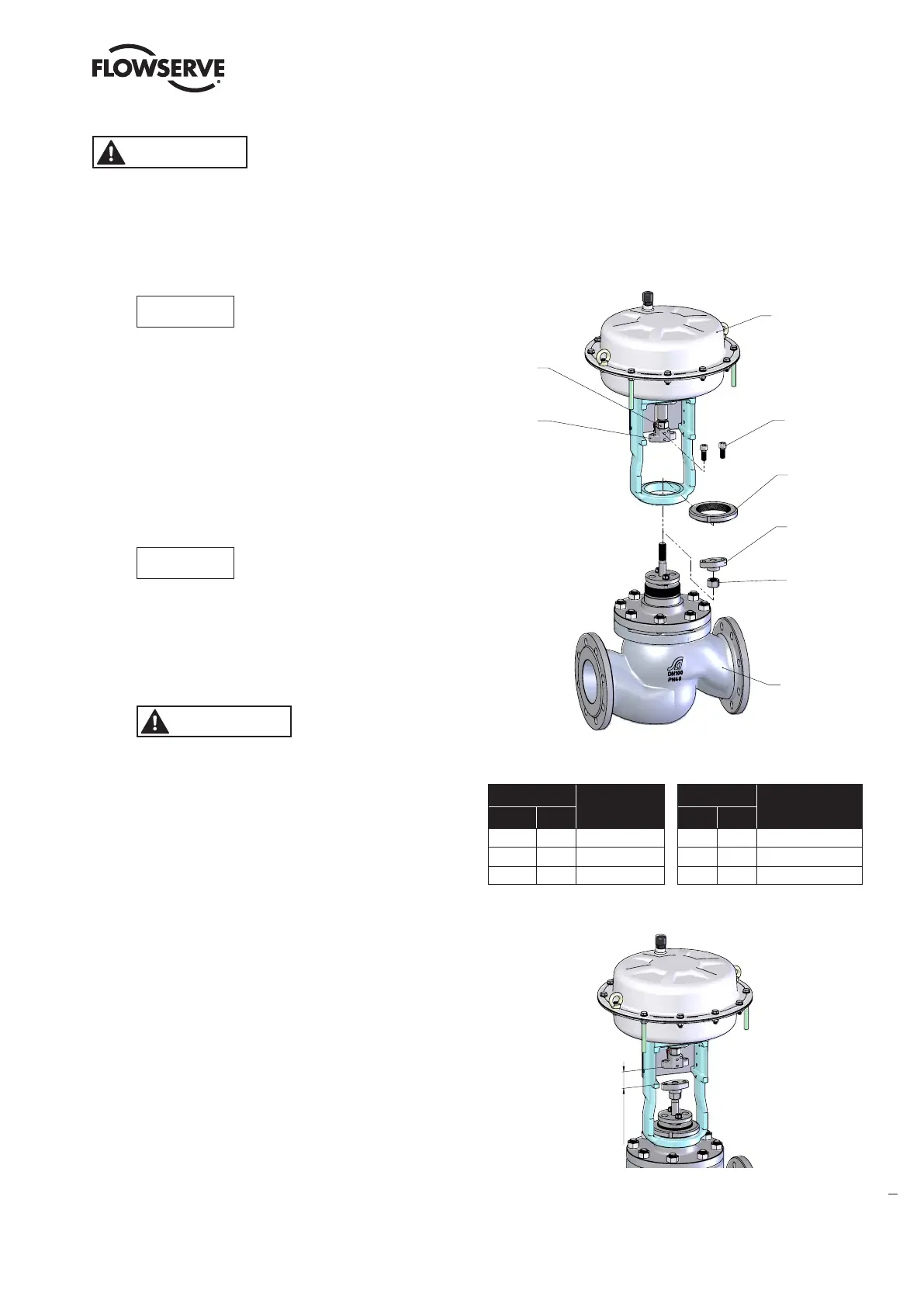
Actuator
240
76
345
113
Valve
249
344
Figure 6: Yoke assembly drawing
Item
Part
Item
Part
WW
EU
WW EU
76 5.10 Yoke lock nut 249 5.3 Upper coupling
113 5.2 Lock nut 344 5.4 Lock nut
240 5.5 Cap screw 345 5.1 Lower coupling
Table 4: Coupling parts identification
Stroke
Figure 7: Stroke adjusting
14. The valve is ready for the mounting of the accessories.