SuperNova Series
S050 - S200
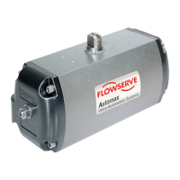
Rack & Pinion AUTOMAX Actuators
Page 1/4
B00043e4-rev2.doc
Installation, Operating & Maintenance Instructions
All actuators are factory lubricated for life, but still should
be protected from the elements and stored indoors until
ready for use. The ports of the actuator are plugged as
supplied from the factory. In case the actuators are stored
a long period before installation, it would be a good practice
to stroke the actuators before mounting. Prior to assembly,
check the mounting surfaces, the stem adaptor and the
bracket to assure proper fit.
Manually open and close the valve to insure freeness of
operation. Be sure the valve and actuator rotate in the
same direction and are in the same position. Secure the
valve with the stem vertical. Bolt the bracket to the valve
and place the stem adaptor on the valve stem. Position the
actuator over the valve and lower to engage the stem
adaptor to the actuator shaft.
Continue to lower until the actuator seats on the bracket
mounting surface. In order to align the bolt holes, it may be
necessary to turn or stroke the actuator a few degrees
and/or adjust the actuator travel stops. Bolt the actuator to
the bracket.
After consulting the valve manufacturer’s
recommendations, adjust the travel stop bolts of the
actuator for the proper open and closed valve positions.
Pneumatically stroke the actuator several times to assure
proper operation with no binding of the stem adaptor. If the
actuator is equipped with limit switches or other
accessories, adjust them at this time.
To prolong actuator life use only clean, dry plant air.
Lubricated air is not required, however it is recommended
particularly for high cycle applications. Do not use
lubricated air with positioners.
Actuator Endcap Screw
Socket Size
Adjustment Bolt
Socket Size
Spring Color
Code
S050 4 mm 3 mm White
S063 5 mm 4 mm Light green
S085 6 mm 5 mm Blue
S100 6 mm 6 mm Red
S115 6 mm 6 mm Yellow
S125 8 mm 6 mm Grey
S150 8 mm 8 mm Dark green
S175 10 mm 8 mm Purple
S200 12 mm 8 mm Orange
Travel Stop Adjustment (Patented)
Both Directions 5° Overtravel
12°Adjustment Each End
The SuperNova Series actuators have unique, patented
travel stop adjustments in both clockwise and
counterclockwise directions. The 10° total overtravel
provides adjustments from –5° to +7° at the “0°”
Counterclockwise position and from +83° to + 95° at the
“90°” Clockwise position.
All actuated valves require accurate travel-stop
adjustments at both ends of the stroke to obtain optimum
performance and valve seat life. The accumulation of
tolerances in the adaption of the actuators to valves is such
that there must be a range of adjustment for both ends of
the stroke to achieve the expected performance.
Ball and Plug Valves require precise adjustment at the
open (CCW) position to protect the seat from the flow
media and the closed (CW) position to assure absolute
shut-off
Butterfly Valves require precise adjustment at the closed
position to assure full shut-off, to prevent disc overtravel
and damage to the seat at the closed position.
Tandem Valves, where two valves are operated in tandem
through a single solenoid valve (eg. A 3-Way
configuration), absolutely require precise adjustment at
both ends of the stroke to assure the seating of both
valves.
Adjustment Bolt Location
Actuator Type Fail
position
Clockwise (CW)
closed
Counterclockwise
(CCW) open
Double Acting Left End Cap Right End Cap
Spring Return CW Left End Cap Right End Cap
Spring Return* CCW* Right End Cap Left End Cap
*The pistons are rotated 180° for CCW fail position