12
Table 4. Levers with hub- applies to sizes 0 and 4-5, and Stem sleeves-
applies to sizes 1-3.
Fig. 16. Installation of end position sensor.
Type of sensor Sensing element Item No.
Magnetic sensor Magnet 100.1
Inductive sensor Steel 100.2
Table 5. Types of end position sensor
The end position indicator kit includes brackets (101),
sensing elements (100.1 and 100.2), screw (33.2) and
transparent protective cover (102) as shown in Fig. 16.
Art. nr. Intended for actuator
349 06 611 791290/92/94-1
349 06 612 791290/92/94-2
349 06 613 791290/92/94-3
Table 6. Part numbers for end position sensors for
actuator sizes 1-3
4.2.1 Fitting the end position sensor
Remove the screws (34) and the window (35). Remove
the white indicating element 833.1) and fit instead the
sensing element (see item 4.2) (100.1 or 100.2) with
the screw (33.2) fitted into the mounting plate (33). Refit
the window (35) together with the brackets (101). Refit
the screws (34). Before tightening the screws, hold the
brackets slightly apart, so that the distance between them
will be at least 18 mm. Fit the selected sensor (103) and
set the required end poistion. The sensor can be adjusted
in height as well as sideways. Finally, fit the protective
cover (102), and secure it in position with its Velcro
locking.
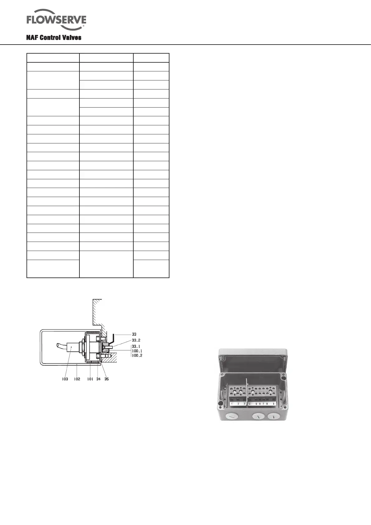
4.3 Junction box
The actuators have mounting holes for fitting a junction
box. The junction box (see Fig. 17) contains terminals
for connecting one solenoid valve and two end position
sensors. The junction box is made of cast aluminium
and has a tightly-seating cover. Degree of protection: IP
65. If the junction box is factor-fitted to the actuator by
NAF, it also contains a wiring diagram for the appropriate
sensors.
Part No. Description
349 04 460 Junction box
Table 7. Part number of junction box
Fig. 17. Junction box
4.4 Solenoid valves
Sizes 0-3
The actuators have mounting holes in accordance with
NAMUR (Fig. 18). Solenoid valves conforming to this
standard can thus be mounted directly on the actuator.
However, first contult NAF if both solenoid valves and end
position sensors are to be fitted.
Actuator size For stem dia. (mm) Part No.
794290/94 - 0 Ø = 16 338 98 630
(Lever with hub
Applies to size 0)
20 333 98 631
25 333 98 632
794290/92/94 - 1 Ø = 16, without keyway 733 94 170
(Stem sleeve.
Applies to all sizes 1-3)
16 333 94 170
20 333 94 160
25 333 94 150
794290/92/94 - 2 Ø = 16, without keyway 733 94 360
16 333 94 360
20 333 94 370
25 333 94 380
30 333 94 390
35 333 94 400
40 333 94 410
794290/92/94 - 3 Ø = 25, without keyway 722 69 420
25 322 69 420
30 322 69 430
35 322 69 440
40 322 69 450
45 322 69 460
50 322 69 470
794290/92/94 - 5 Third digit in actuator
size designation
specifies the stem hole
in mm in the lever
(Stem sleeve.
Applies to all sizes 1-3)
 Loading...