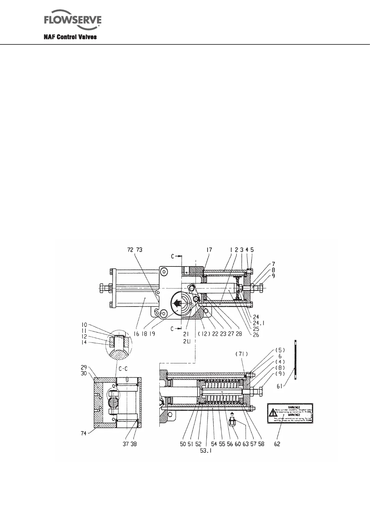
17
17 O-ring 2 4 for size 0
18 Screw 4 8 for size 0
19 Visual indicator 1
20 Stem sleeve 1 None for size 0
21 Lever 1
21 .1 Bush 2 Not shown in figure.
None for size 0
22 Circlip 4
23 Pin 2
24 Nut 2
24 .1 Washer 2
25 Piston 1 (size 11, 21, 31)
Fitted on side A.
2 (size 02, 12, 22, 32)
26 Piston rod 1
Item Description Qty/ Remarks
No. actuator
27 O-ring 2 (size 0)
27 Faced O-ring 2 (size 1 - 3)
28 Piston rod bush 2
29 Cover 1
30 Housing 1
31 * Coupling 1
32 * Drive screw 2
33 * Mounting plate 1
33 .1* Indicating unit 1
33 .2* Screw 1
34 * Screw 6 o 8 Depends on size
35 * Window 1
36 * Circlip 1
37 O-ring 2
38 Lever bearing 2
Item Description Qty / Remarks
No. actuator
Side B
Side A
*Not in size 0, since there is no window and stem sleeve
Fig. 19.0. Locations of components of size 02
 Loading...