0000137242 Rev. 7.1 6
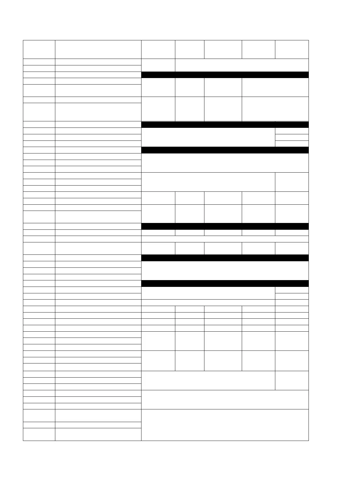
2.2.3 ELECTRICAL CONNECTIONS TABLE
Chlorine/Br
omine
PH-
Redox
Chlorine/
Bromine
Bromine -
Redox
Redox-NTU
1 pH probe (+)
Not Used PH probe input
2 pH probe (-)
3 - 4 Not used
5 Redox probe (+)
Not Used
Redox
probe
input
Not Used Redox probe input
6 Redox probe (-)
7 Amp Chlorine Probe (+)
Chlorine
Bromine
probe input
(CU-PT)
Not Used
Chlorine
Bromine
probe input
(CU-PT)
Chlorine/ Bromine probe
input (CU-PT)
8 Amp Chlorine Probe (-)
9-10 Not used
11 NTU
Not used
+24V
12 NTU In mA
13 NTU GND
14-16 Not used
17 Temperature Probe (Green)
PT100 or PT1000 Temperature Probe Input 18 Temperature Probe (Blue)
19 Temperature Probe (Yellow)
20 +5Vdc
Flow Meter Input
Not used 21 Input frequency
22 GND
23 Freq. output (+)
Not Used pH pH pH pH
24 Freq. output (-)
25 Freq. output (+)
Chlorine/
Bromine
Redox
Chlorine/
Bromine
Chlorine/
Bromine
Chlorine
26 Freq. output (-)
27 - 30 Not used
31 Current output (+) Not Used PH PH PH PH
32 Gnd Current output (-) Output current GND connector
33 Current output (+)
Chlorine
Bromine
Redox
Chlorine
Bromine
Chlorine
Bromine
Chlorine
34 - 36 Not used
37 RS 485 -
RS485 Serial Port
with ModBus RTU protocol
38 RS 485 +
39 RS 485 GND
40 Not used
41 HOLD +
15 to 30 Vdc voltage input
42 HOLD -
43 - 44 REED REED sensor input
45 - 46 Level 1 Signal Not Used PH PH PH PH
47 - 48 Level 2 Signal Chlorine Redox Chlorine Chlorine Chlorine
49 - 50 Relay 1 output (dry contact) Alarm Alarm Alarm Alarm Alarm
51 - 52 Relay 2 output (dry contact) Not Used Not Used Not Used Redox Redox
53 Relay phase (100 to 240Vac) Not Used
pH relay pH relay pH relay pH relay 54 Ground
55 Relay neutral (100 to 240 Vac)
56 Relay phase (100 to 240Vac)
Chlorine/
Bromine
relay
Redox
relay
Chlorine
/Bromine
relay
Chlorine/
Bromine
relay
Chlorine
relay
57 Ground
58 Relay neutral (100 to 240 Vac)
59 Relay phase (100 to 240Vac)
Temperature Relay
NTU /
Temperatur
e Relay
60 Ground
61 Relay neutral (100 to 240 Vac)
62 Relay phase (100 to 240Vac)
Time relay 63 Ground
64 Relay neutral (100 to 240 Vac)
65 Power supply phase(100 to 40
Vac)
100 to 240 Vac 50/60 Hz Power Supply Connector 66 Ground
67 Power supply neutral (100 to 240
Vac)
Example of the Connections Label affixed to the back of the instrument’s connections compartment.