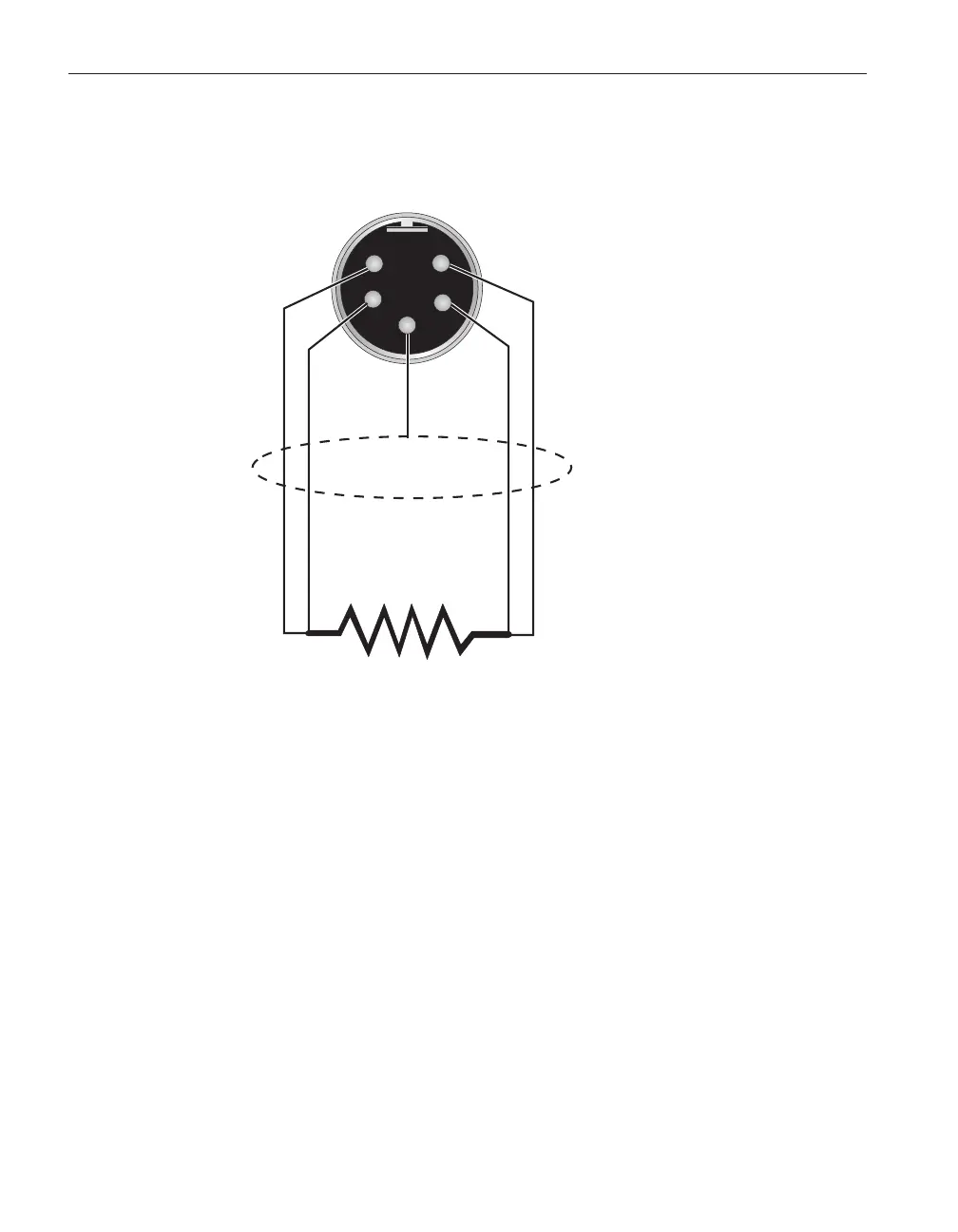
to pins 4 and 5. (Pins 1 and 5 source current and pins 2 and 4 sense the poten
-
tial.) If a shield wire is present it should be connected to pin 3.
A two-wire probe can also be used with the 1502A. It is connected by attaching
one wire to both pins 1 and 2 of the plug and the other wire to both pins 4 and
5. If a shield wire is present it should be connected to pin 3. Accuracy may be
significantly degraded using a two-wire connection because of lead resistance.
1502A Thermometer Readout
User’s Guide
12
1
2
4
5
RTD Sensor
Probe Connector
3
Shield
Figure 1 Connecting a four-wire probe