Do you have a question about the Fluke Hart Scientific 1575 Super-Thermometer and is the answer not in the manual?
Lists symbols used in the manual and on the instrument.
Provides safety warnings and definitions for hazards.
Identifies conditions and actions that may pose hazards to the user.
Identifies conditions and actions that may damage the instrument.
Lists authorized service centers for product support and repairs.
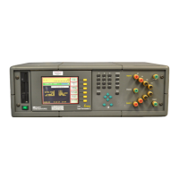
Describes the 1575/1590 Super-Thermometer and its capabilities.
Explains the electronic design and measurement principles of the instrument.
Details the resistance ratio measurement method used by the instrument.
Discusses sources of error and how the instrument addresses them.
Explains how lead resistance is eliminated using a four-wire circuit.
Details how thermoelectric EMF errors are canceled using a specific technique.
Explains how DC circuitry minimizes errors from reactance.
Discusses how DC operation ensures accuracy with minimal leakage.
Explains how self-heating is controlled via current adjustment.
Describes how component drift is managed through self-calibration.
Discusses sources of noise and how resolution is achieved.
Details steps taken to minimize nonlinearity for precise measurements.
Highlights the instrument's fast measurement capability (2 seconds per measurement).
Explains the benefits of the semiconductor circuit design for reliability and cost.
Lists detailed electrical and performance specifications for the instrument.
Outlines acceptable operating temperature, humidity, and pressure ranges.
Details the product warranty terms and conditions provided by the manufacturer.
Guides the user on how to unpack the instrument and verify contents.
Advises users to familiarize themselves with the instrument's features and components.
Directs users to relevant sections for setting up the optional scanners.
Explains how to select and set the correct input voltage for the instrument.
Details how to connect the SPRT or thermistor probe using the DWF connectors.
Instructs on how to turn the instrument on and what to expect during startup.
Provides a step-by-step guide for setting up and taking temperature measurements.
Describes the components and controls found on the front panel of the instrument.
Details the connectors and controls located on the rear panel of the instrument.
Explains the features and data displayed on the instrument's LCD screen.
Describes the functions of the various buttons on the front panel.
Lists various applications for which the 1575/1590 thermometer is well-suited.
Provides tips and recommendations for achieving the best measurement results.
Offers detailed suggestions on how to maintain measurement accuracy.
Explains how to determine the instrument's contribution to total system uncertainty.
Addresses frequently asked questions regarding the instrument's functionality.
Explains how to select and manage input channels for measurements.
Details how to select the second input channel for measurements.
Describes the mode for automatically switching between input channels.
Covers functions for controlling sampling, timing, and statistics.
Explains how to start and stop the data sampling process.
Details how to program the instrument for a specific number of measurements.
Describes parameters for setting conversion time, sample interval, and integration period.
Explains how the digital filter removes noise and improves measurement resolution.
Explains how to clear statistical registers for new calculations.
Covers functions for storing and retrieving measurements in memory.
Details how to store the most recent measurement into a memory location.
Explains how to enter arbitrary values into memory locations.
Describes how to scan and view the data stored in the instrument's memory.
Explains how to clear the instrument's memory contents.
Details how to temporarily stop or resume data sampling.
Covers functions for specifying probe parameters and calibration.
Explains how to select the input channel for probe parameter editing.
Describes how to choose a probe definition for a selected channel.
Details how to set parameters like serial number, conversion type, and current for a probe.
Explains how to enter or read the probe’s serial number.
Details the algorithms used to convert resistance to temperature.
Explains how to use the ITS-90 standard for temperature conversion and calibration.
Describes the IPTS-68 option for probes calibrated to the 1968 scale.
Explains the Callendar-Van Dusen conversion for industrial probes.
Details using polynomial equations for non-standard temperature sensors.
Explains using Steinhart-Hart equations for thermistor conversion.
Describes how to display measurements directly as resistance in ohms.
Explains displaying ITS-90 resistance ratio W(T90).
Details displaying measurements as a resistance ratio.
Explains selecting the appropriate reference resistor for measurements.
Discusses optimizing driving current for accurate measurements and minimizing self-heating.
Explains the standby current feature for channels not actively measured.
Describes how to compensate for lead resistance in two/three-wire measurements.
Covers functions for calibrating probes to ensure accuracy.
Details the process for calibrating the probe at the triple point of water.
Guides through calibrating probes to the ITS-90 standard and calculating coefficients.
Describes calibration using fixed-point temperatures and resistance measurements.
Explains manual sequencing for comparison calibration with a reference SPRT.
Details automatic sequencing for comparative calibration, useful for multi-probe setups.
Describes calibration using SPRT as a reference resistor for improved accuracy.
Explains calibration using W values obtained from fixed points for higher precision.
Details setting up calibration parameters, probes, and channels.
Explains how to calculate ITS-90 coefficients from measured data.
Guides on printing calibration reports and resistance tables.
Explains using increased current to measure self-heating error.
Details restoring the original current after self-heating tests.
Describes testing temperature conversion accuracy with entered resistance values.
Covers functions for reading, writing, and formatting probe data on disk.
Explains how to save individual probe parameter sets to disk.
Details how to load probe parameter sets from disk.
Describes saving all probe parameter sets to disk at once.
Explains loading all probe parameter sets from disk.
Guides on formatting floppy disks for use with the instrument.
Covers setting up the display to show desired measurements and data.
Explains selecting between data and graph display modes.
Details how to choose from various display configurations.
Guides on programming the five data fields in the data display.
Explains setting graph limits and style for visualization.
Describes how to select the resolution for displayed measurements.
Explains how to clear graph data and rescale the display.
Covers functions for controlling temperature units, time, and communications.
Details how to select measurement units (C, F, K, etc.).
Covers saving/loading parameters, and setting date/time.
Explains how to set the instrument's date and time.
Guides on saving the instrument's configuration parameters to disk.
Details how to load saved instrument parameters from disk.
Explains how to reset all instrument parameters to factory defaults.
Covers settings for screen saver, brightness, and colors.
Covers functions for setting up disk data logging and formatting disks.
Covers setting up serial, IEEE-488, and printer interfaces.
Details configuring the RS-232 serial interface for communication.
Explains configuring the IEEE-488 (GPIB) interface for system integration.
Describes connecting a printer for recording measurements.
Explains setting up the analog output for measurement signal representation.
Details specifying the channel and measurement parameter for analog output.
Explains setting the resolution for the analog output signal.
Describes setting the offset for the analog output voltage.
Explains using the center function to set the analog output offset.
Details calibrating the analog output for improved accuracy.
Covers setting/calibrating reference resistors and security lock-out.
Explains how to configure the instrument for an external reference resistor.
Details setting internal reference resistor values and the oven.
Describes the procedure for calibrating the internal reference resistors.
Covers locking out parameters and functions with a password.
Lists recommended standard resistors for calibration and verification.
Details the procedure for calibrating the instrument's resistance ratio accuracy.
Explains calibrating the internal reference resistors using standard resistors.
Introduces the 2575 ten-channel scanner and its function with the thermometer.
Lists the technical specifications for the 2575 scanner.
Provides basic setup instructions for the 2575 scanner.
Details the necessary cable connections between the scanner and thermometer.
Explains connecting the scanner's output to the thermometer's input.
Details connecting the control cable for scanner operation.
Explains connecting probes to the scanner's input terminals.
Guides on setting up the scanner with the thermometer for measurements.
Describes the components and controls on the 2575 scanner's front panel.
Introduces the 2590 ten-channel scanner for the 1590 thermometer.
Lists the technical specifications for the 2590 scanner.
Provides basic setup instructions for the 2590 scanner.
Details the necessary cable connections between the scanner and thermometer.
Explains connecting the scanner's output to the thermometer's input.
Details connecting the control cable for scanner operation.
Explains connecting probes to the scanner's input terminals.
Guides on setting up the scanner with the thermometer for measurements.
Describes the components and controls on the 2590 scanner's front panel.
Lists common problems and their likely causes and solutions.
| Brand | Fluke |
|---|---|
| Model | Hart Scientific 1575 Super-Thermometer |
| Category | Thermometer |
| Language | English |