1630-2/1630-2 FC
Calibration Manual
8
Performance Verification
Before you do the verification:
1. Make sure that you have the required equipment. See Table 4.
2. Make sure the Product battery is good and replace it if necessary.
3. Warm up the Calibrator as necessary. Refer to its specifications.
4. Let the temperature of the unit under test (UUT) become stable to room temperature.
5. Use the loop of wire to apply signals to the 1630-2. The loop should have a straight section that goes through
the jaws. A 2-foot section of 16-gauge copper wire makes a good, stable loop.
Note
The loop has resistance that will have to be included in the applied resistance. The
2-foot section of 16-gauge copper wire adds about 0.01 Ω. Make a 4-wire
measurement of the loop to include in the applied resistance.
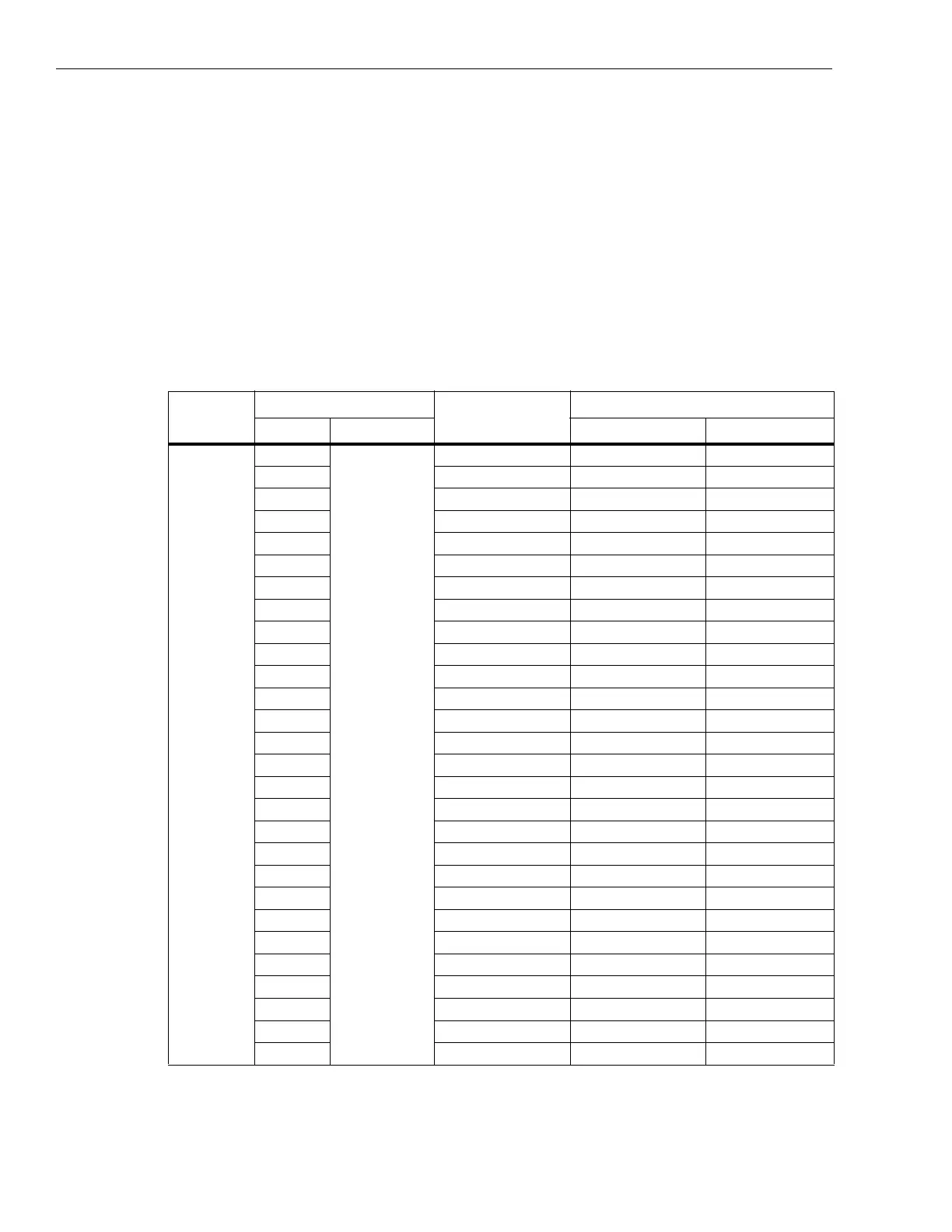
Table 4. Performance Test Points for Resistance
Function
Test Point
Applied Resistance
Display Reading
Value Unit Lower Limit Upper Limit
OHM
0.080
Ω
0.080 – Loop Ω 0.059 0.101
0.120 0.120 – Loop Ω 0.098 0.142
0.230 0.230 – Loop Ω 0.207 0.253
0.280 0.280 – Loop Ω 0.226 0.334
0.450 0.450 – Loop Ω 0.393 0.507
0.550 0.550 – Loop Ω 0.492 0.608
0.900 0.900 – Loop Ω 0.837 0.964
1.100 1.100 – Loop Ω 0.984 1.217
1.800 1.800 – Loop Ω 1.673 1.927
2.300 2.300 – Loop Ω 2.166 2.435
4.500 4.500 – Loop Ω 4.333 4.668
5.500 5.500 – Loop Ω 5.318 5.683
8.000 8.000 – Loop Ω 7.780 8.220
11.00 11.00 – Loop Ω 10.54 11.47
18.00 18.00 – Loop Ω 17.43 18.57
23.00 23.00 – Loop Ω 22.36 23.65
40.00 40.00 – Loop Ω 39.10 40.90
60.00 60.00 58.60 61.40
90.00 90.00 88.15 91.85
120.0 120.0 115.4 124.6
180.0 180.0 173.6 186.4
220.0 220.0 204.0 236.0
360.0 360.0 337.0 383.0
450 450 395 505
550 550 485 615
700 700 560 840
900 900 720 1080
1300 1300 1040 1560

 Loading...