175, 177, & 179
Calibration Information
6
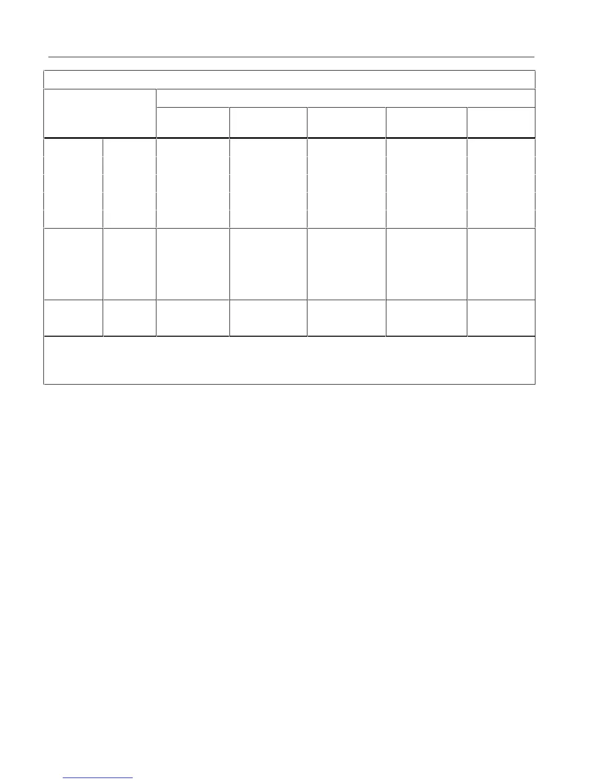
Frequency Counter Sensitivity
Typical Sensitivity (RMS Sine Wave)
Input Range
1, 2
2 Hz to 45 Hz
45 Hz to
10 kHz
10 kHz to
20 kHz
20 kHz to
50 kHz
50 kHz to
100 kHz
Volts AC 600 mV Unspecified
3
80 mV 150 mV 400 mV Unspecified
3
6 V 0.5 V 0.6 V 1.0 V 2.8 V Unspecified
3
60 V 5 V 3.8 V 4.1 V 5.6 V 9.6 V
600 V 50 V 36 V 39 V 45 V 58 V
1000 V 500 300 V 320 V 380 V NA
Volts DC 6 V 0.5 V 0.75 V 1.4 V 4.0 V Unspecified
3
60 V 4 V 3.8 V 4.3 V 6.6 V 13 V
600 V 40 V 36 V 39 V 45 V 58 V
1000 V 500 V 300 V 320 V 380 V NA
AC/DC Amps mA 5 mA 4 mA 4 mA 4 mA
4
NA
A 0.5 A 0.4 A 0.4 A 0.4 A
4
NA
1. Maximum input for specified accuracy = 10 x Range or 1000 V.
2. Noise at low frequency and amplitude may exceed the frequency accuracy specification.
3. Unspecified but usable depending on quality and amplitude of signal.
4. In mA and A ranges, frequency measurement is specified to 30 kHz.
Testing the Fuses
WWarning
To avoid electrical shock or personal injury:
•
Remove the test leads and any input signals before replacing the battery or
fuses.
•
To avoid electrical shock, arc blast, or damage to the Meter, install only
fuses with the amperage, interrupt, and voltage, and speed ratings specified
in Table 5.
To test the fuses (refer to Figure 1):
1. Set the rotary switch to e.
2. Plug a test lead into the VeG terminal and touch the probe to the
400 mA (to test the 440 mA fuse)
or
10 A terminal (to test the 11 A fuse).
• If the display shows a resistance value in the range shown in Figure 1, the fuse is good.
• If the display reads
OL, replace the fuse and test again.
• If the display shows any other value have the Meter serviced. See “Service Information” earlier in
this manual.

 Loading...