Theory of Operation
Automatic Selection Input Resistance
2
2-5
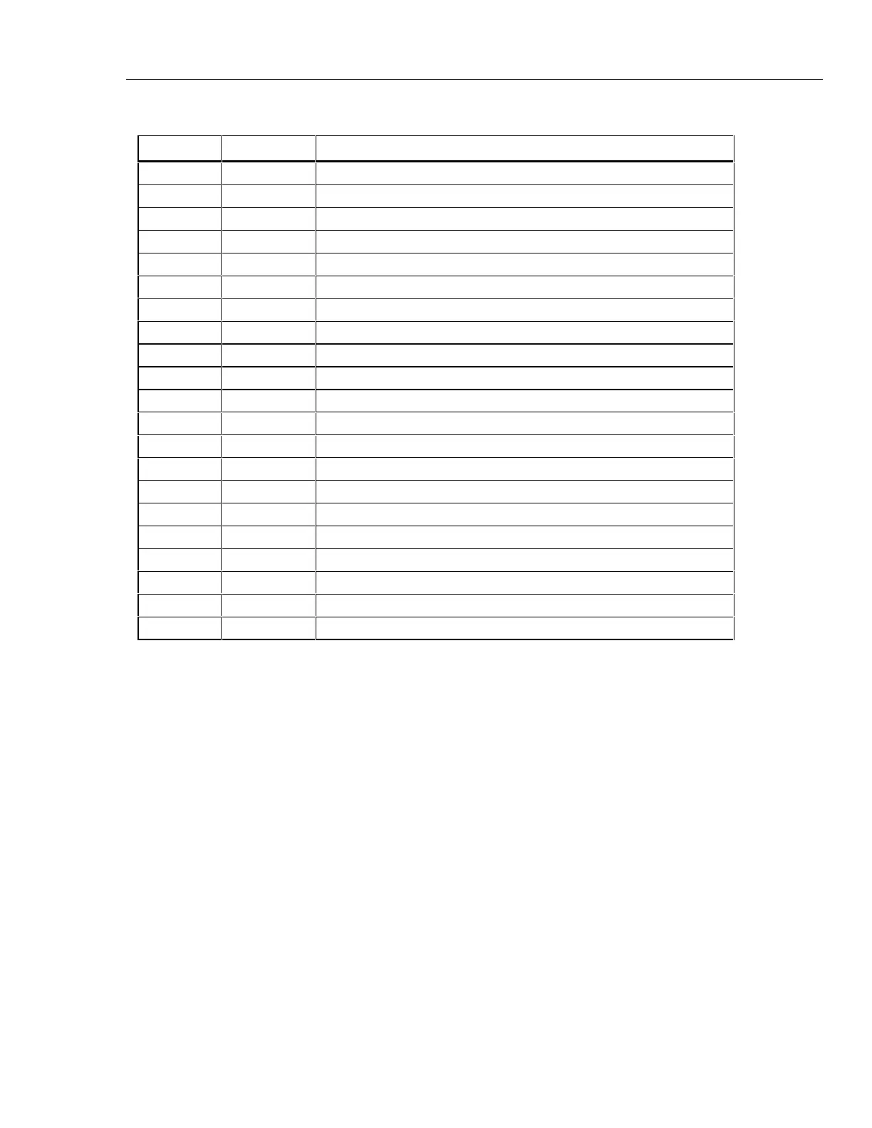
Table 2-2 U1 Pinout Table (continued)
Pin No. Pin Name Description
40 APV0 DC volts input pin from 10 MΩ resistor
41 DIVLO Input divider (Z1) common (low) pin
42 APV1 10-to-1 voltage divider and 1 MΩ reference resistor input
43 APV2 100-to-1 voltage divider and 100 kΩ reference resistor input
44 APV3 1000-to-1 voltage divider and 10 kΩ reference resistor input
45 APV4 10,000-to-1 voltage divider and 1 kΩ reference resistor input
46 GND Ground power supply pin connected to common (digital ground)
47 DATA3 Most significant bidirectional data bus line
48 DATA2 Bit 2 of parallel data bus
49 DATA1 Bit 1 of parallel data bus
50 DATA0 Least significant bidirectional data bus line
51 N/C No connection
52 BEEPER (L) One of two beeper drive lines. Voltage swings VDD to VSS.
53 VSS Negative power supply line (-3V relative to DGNG)
54 VSS Negative power supply line (-3V relative to DGNG)
55 CLK System clock line from U2. 131,072 Hz.
56 BCLK Beeper frequency (2.3 kHz) clock line from U2
57 TESTCLK Test clock pin for U1 testing
58 BEEPER One of two beeper drive lines. Voltage swings VDD to VSS.
59 N/C No connection
60 WRITE (L) When driven low (VSS), data is written to addressed register
 Loading...


