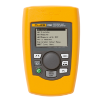
Loop Calibrator
Calibration Adjustment Procedure
7
Table 4. DC Current Source / Current Measure / Voltage Measure Mode Tests
Test No. 705 Loop Calibrator Output Switch
Position
HP 3458A Minimum HP 3458A Maximum
1
2
3
4.000 mA
12.000 mA
24.000 mA
Center
Center
Center
3.997 mA
11.995 mA
23.993 mA
4.003 mA
2.005 mA
24.007 mA
5500A Calibrator Output Switch
Position
Fluke 705 Minimum Fluke 705 Maximum
4
5
6
4.000 mA
12.000 mA
24.000 mA
Center
Center
Center
3.997 mA
11.995 mA
23.993 mA
4.003 mA
12.005 mA
24.007 mA
5500A Calibrator Output Switch
Position
Fluke 705 Minimum Fluke 705 Maximum
7
8
9
0.000 V
14.000 V
28.000 V
Right
Right
Right
-0.001 V
13.995 V
27.992 V
0.001 V
14.005 V
28.008 V
DC Current Measurement Mode
1. Set the rotary switch on the Loop Calibrator to
V MEASURE.
The Loop Calibrator’s display should read V.
2. Connect the test leads from the output NORMAL
terminals of the Fluke 5500A to the input
terminals on the Loop Calibrator (Black to COM
and red to [+] ).
3. Set the Fluke 5500A to test 7 in Table 4 and
verify the display reading on the Loop Calibrator.
Repeat for tests 8 and 9.
The reading on the display should be within the
minimum and maximum values shown in
Table 4.
4. Set 5500A output to 0 V (zero), and set output to
STANDBY.
5. Turn the rotary switch of the Loop Calibrator to
OFF and disconnect the Loop Calibrator from the
5500A.
The performance verification tests are now
complete.
If the Loop Calibrator failed any of these tests,
calibration adjustment or repair is required.
Calibration Adjustment Procedure
Perform the following calibration adjustment
procedures if the Loop Calibrator fails the
performance verification test.
Notes
Make sure that the Loop Calibrator has a
new battery before starting the calibration
procedure. Calibration will not function
properly if low battery indicator M is on.
Because the Fluke 705 Loop Calibrator
incorporates several key hold start up
features, entering the CAL mode through the
keypad requires an exact key hold sequence.
1. With the rotary switch in the
OFF position, hold
down the Pkey and turn the rotary switch to V
MEASURE
.
2. When
CAL appears, press and hold the P and
the M keys. Immediately release both keys when
CAL disappears. Verify that the display shows
MEASURE 0.000V with no – sign or fluctuating
digits. If it does not, CAL mode has not been
successfully entered.
3. Connect the test leads from the output
NORMAL
terminals of the Fluke 5500A to the terminals on
the Loop Calibrator (Black to COM and red
to [+] ).