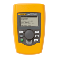
Fluke 707
Calibration Information
6
Recommended Test Equipment
A list of recommended equipment for the
performance verification tests and calibration
adjustment procedure is shown in Table 3.
Performance Verification
W Warning
To prevent electric shock, do not perform
the verification tests unless the Loop
Calibrator is fully assembled.
Perform the following tests to check the accuracy of
each of the Loop Calibrator’s functions against its
specifications.
If the Loop Calibrator fails any of these tests,
calibration adjustment or repair is required.
Performance Verification Procedures
DC Current Source Mode
Test 1:
1. Turn the Loop Calibrator on.
After the P.S. power timeout displays, the Loop
Calibrator should display 4.000 mA. If it is
displaying 0.000 mA, turn the Loop Calibrator
off. Hold down
while turning the Loop
Calibrator on. Continue to hold for 2 seconds.
When the timeout display ends, the Loop
Calibrator should display 4.000 mA.
2. Connect the Loop Calibrator’s [+] terminal to the
HP 3458A I input, and the COM terminal to the
HP 3458A LO input.
3. Verify that the Loop Calibrator's display shows
SOURCE in the upper-left corner.
4. Set the HP 3458A to measure DC Amps (
DCI).
5. Refer to Table 4 to verify the readings on the HP
3458A for the following tests. (No adjustment is
necessary for test 1.)
Test 2:
1. Press
twice to select 12.000 mA.
2. Verify the readings.
Test 3:
1. Press
twice to select 20.000 mA.
2. Press and rotate the knob until 24.000 mA is
displayed.
3. Verify the readings.
DC Current Measurement Mode
Test 4:
1. Press the
key twice to put the Loop Calibrator
into the mA measurement mode.
The Loop Calibrator’s display should show
MEASURE in the top right corner.
2. Disconnect the HP 3458A from the Loop
Calibrator.
3. Connect the test leads from the
red AUX terminal
of the Fluke 5520A to the HP 3458A I input.
4. Connect a test lead from the
black AUX terminal
of the Fluke 5520A to the COM terminal on the
Loop Calibrator.
5. Connect a test lead from the HP 3458A LO input
to the Loop Calibrator's + terminal.
6. Adjust the Fluke 5520A to output the value of
test 4 in Table 2 as measured by the HP 3458A.
7. Adjust the Fluke 5520A if necessary, the reading
on the HP 3458A is the same as the value for the
5520A in steps 4-6 in Table 4.
8. Verify the display readings on the Loop
Calibrator.
Table 3. Recommended Equipment
Equipment Recommended Model or Equivalent
DC Calibrator DC Voltage: 0 to 30 V
Accuracy: ± 0.004 % +0.5 mV
DC Current: 0 to 24 mA
Accuracy: ± 0.004% +0.5 µA
Fluke 5520A Multi-Product Calibrator
Digital Multimeter DC Current: 0 to 26 mA
Accuracy: ± 0.004% +0.5 µA
HP 3458A

 Loading...