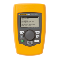
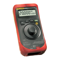
Loop Calibrator
Calibration Adjustment
7
Table 4. DC Current Source / Current Measure / Voltage Measure Mode Tests
Test No. 707 Loop Calibrator Output Mode HP 3458A Minimum HP 3458A Maximum
1
2
3
4.000 mA
12.000 mA
24.000 mA
mA Source
mA Source
mA Source
3.9974 mA
11.9962 mA
23.9944 mA
4.0026 mA
12.0038 mA
24.0056 mA
Test No. 5520A Calibrator Output Mode Fluke 707 Minimum Fluke 707 Maximum
4
5
6
4.000 mA
12.000 mA
24.000 mA
mA Measure
mA Measure
mA Measure
3.997 mA
11.996 mA
23.994 mA
4.003 mA
12.004 mA
24.006 mA
Test No. 5500A Calibrator Output Mode Fluke 707 Minimum Fluke 707 Maximum
7
8
9
0.000 V
14.000 V
28.000 V
Volt Measure
Volt Measure
Volt Measure
-0.002 V
13.996 V
27.994 V
0.002 V
14.004 V
28.006 V
DC Voltage Measurement Mode
1. Press twice to get the Loop Calibrator to
V MEASURE. The Loop Calibrator’s display
should read "V".
2. Connect the test leads from the NORMAL output
terminals of the Fluke 5520A to the input
terminals on the Loop Calibrator (black to COM
and red to [+] ).
3. Set the Fluke 5520A to test 7 in Table 4 and
verify the display reading on the Loop Calibrator.
4. Repeat for tests 8 and 9.
The reading on the display should be within the
minimum and maximum values shown in
Table 4.
5. Set the 5520A output to 0 V (zero), and set output
to
STANDBY.
6. Turn the Loop Calibrator
OFF and disconnect the
Loop Calibrator from the 5520A.
The performance verification tests are now
complete.
If the Loop Calibrator failed any of these tests,
calibration adjustment or repair is required.
Calibration Adjustment
Perform the following calibration adjustment
procedures if the Loop Calibrator fails the
performance verification test.
Calibration Adjustment Counter
The Loop Calibrator contains a calibration
adjustment counter. The value in the calibration
adjustment counter can be recorded and used to show
that no adjustments have been made during a
calibration cycle. When Fluke performs the
calibration, the value of the calibration adjustment
counter will be recorded on the calibration label.
To find the value in the calibration adjustment
counter, hold down
while turning the unit on. The
software revision will display for 2 seconds followed
by the calibration counter for another 2 seconds.
Note
Make sure that the Loop Calibrator has a
new battery before starting the calibration
procedure. Calibration will not function
properly if the low battery indicator ( M) is
on.
Because the Loop Calibrator incorporates several key
hold start up features, entering the Adjust mode
through the keypad requires an exact key hold
sequence:
1. With the Loop Calibrator off, hold down
and and turn the Loop Calibrator on.
"
CAL" appears on the main display and the
calibration adjustment counter is displayed on the
secondary display. If the knob is not turned
within 2 seconds, the unit returns to the normal
operation mode.

 Loading...