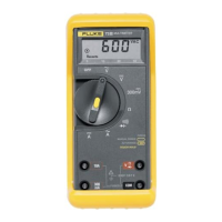
732A
Table
2-1,
732A Front
Panel
Controls and
Adjustments
ITEM
FEATURE NAME
DESCRIPTION
1
1.018V
Adjustment*
Calibration
tool adjustment.
±50
pV adjust
for
1,018V
output.
2 1V Adjustment*
Calibration
tool
adjustment.
±5
adjust
for
IV output.
3 10V Adjustment*
Calibration
tool
adjustment
±50
fj\/
adjust for 10V
output.
4
AC PWR
Indicator
LED
that
indicates
the
presence
of
ac
power when
illuminated.
5 BTRY
CHG
Indicator
LED
that
indicates
battery charger
operation
when
illuminated.
6 IN
CAL
Indicator**
LED
that
indicates
out-of-calibration
condition
when not
illuminated.
7 RESET**
Terminal
behind front
panel to
reset the IN CAL indicator
to ON
condition.
8
GUARD Terminal
Binding
post
that
connects to
internal
Guard circuit. Normally
connected
to OUTPUT
LO
at
some point
in the measurement
system. 60V
is
the
maximum
differential
allowed
between
GUARD
and
CHASSIS
GROUND.
9
CHASSIS
GROUND Terminal
Binding
post connected
to
the
chassis
of
the
732A.
10
IV HI Terminal
Binding
post on which the
1V
output
of
732A
Is
available.
11
LO
Terminal
Binding
post which
provides
common
connection for
the 10V
output.
12
LO Terminal
Binding
post which
provides
common
connection
for
the IV
and
1.018V
outputs.
13
10V HI Terminal
Binding
post on which
the
10V output of the 732A
Is
available.
14
1.018V HI Terminal
Binding
post on which
the 1.018V
output of the
732A
is available.
15
OVEN
TEMP
THERMISTOR
terminals
3/4-inch
spaced
dual
binding
posts.
Floating
thermistor
for
monitoring
oven
temperature.
*The 10V adjustment affects both
the
1.018V and 1
V
outputs.
This
adjustment
should
be made first when
calibrating the 732A. See Section 4.
“The IN CAL indicator detects an
out-of-range
condition
within
the power
supply
of the 732A.
If
not
illuminated, the 732A is not operating
at its specified
accuracy.
Use the RESET
terminal
to restore the IN
CAL
indicator
after
re-calibration.
See
Section
4.
Table
2-2.
T32A
Rear Panel Features and Controls
FEATURE NAME DESCRIPTION
1
AC
Module
Rear
panel module
containing
the A3,
Pre-Regulator
PCB Assembly.
2
Battery
Module
Rear
panel
module
containing
the
A6A1,
Battery PCB
Assembly.
3
SUPPLY
SETTING
(Ac power requirements)
Specifies the
correct
ac line
voltage required
to
operate the instrument.
4
^
chassis
terminal
Binding
post that
provides
a direct chassis
connection.
5
BATTERY OPR
switch Slide
switch
that
sets
instrument
back-up battery supply,
on or off.
6
POWER
INPUT
jacks
Dual %-inch
spaced banana
jacks for
connecting
an external
power
source (24-40V
dc
or
24-30V ac,
50-440
Hz).
The
internal
back-up
battery
voltage may
also
be measured
at these
jacks.
2-4