Maintenance
Performance Tests 3
3-9
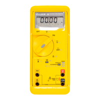
Display Test 3-13.
To test the display, turn the UUT on and check whether all display segments come on as
indicated in Figure 3-4.
H
_
+
_
+
0 2001 400 2 600 3600 4100
mV
mV AC
mV DC
Mk Hz
n F
m
l9f.eps
Figure 3-4. Display
DC Voltage Test 3-14.
1. Set the UUT function switch to V DC and connect the DC Voltage Calibrator output
to the VΩ and COM input terminals of the UUT.
2. Referring to Table 3-2, set the DC Voltage Calibrator for the output indicated in steps
1 through 4 only. Verify that the UUT display reading is within the limits shown.
3. Reset the source to 0V.
Table 3-2. DC Voltage Test
Step
Input
Display Reading
Range Voltage
1 4V short 0 to ± .001 V DC
2 4V +3.5V 3.488 to 3.512V DC
3 4V
-3.5V -3.488 to -3.512V DC
(and within 2 counts
of +3.5V reading)
4 40V +35V 34.88 to 35.12V DC
5 400V +350V 348.8 to 351.2V DC
6 600V +600V 597 to 603V DC
mV DC Test 3-15.
1. Set the UUT function switch to mV DC, and connect the DC Voltage Calibrator
output to the VΩ and COM input terminals of the UUT.
Note
For autorange, press and hold the push button for 1 second.
2. Referring to Table 3-3, set the DC Voltage Calibrator to the voltage indicated in the
steps. Verify that the UUT display reading is within the limits shown.
3. Reset the source to 0V.

 Loading...