80 Series V
Calibration Manual
10
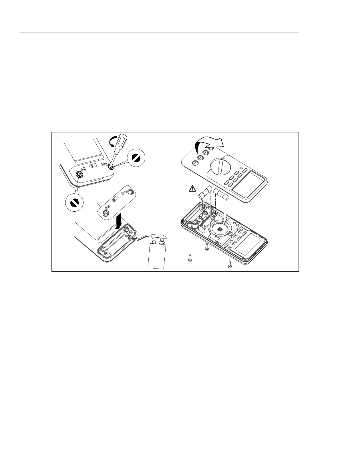
WCaution
To avoid damaging the Meter, the gasket that is sealed to the
bottom case, and is between the two case halves, must remain
with the case bottom. The case top lifts away from the gasket
easily. Do not damage the gasket or attempt to separate the
case bottom from the gasket.
4. Hold the Meter display side up.
5. Pushing up from the inside of the battery compartment, disengage the case top from
the gasket.
6. Gently unsnap the case top at the display end, see Figure 1.
F1
F2
ama12.eps
Figure 1. Opening the Meter, Battery and Fuse Replacement
Accessing the PCA and Replacing the LCD
Once the case has been opened, the A1 Main PCA can easily be removed. The shields
disconnect from the PCA as follows:
1. Remove the five Phillips-head screw securing the top and bottom shields to the PCA.
2. Remove the top shield assembly that also houses the LCD and lightpipe for the LCD
backlight.
3. To access the LCD, unsnap the LCD mask using a small flat-blade screwdriver. The
LCD may now be removed. Refer to Figure 2.
Note
Two elastomeric connectors make electrical contact between the LCD and
the PCA. These connectors usually stick to the LCD when it is removed. If
the connectors are to be reused, do not handle them, as the electrical
contact points might become contaminated. Use tweezers to remove these
connectors.
4. To reinstall the connectors, replace the LCD and LCD mask and lay the top shield
face down. Install the elastomeric connector strips into the slots on the top shield.

 Loading...