Digital Multimeter
Required Equipment
13
MIN MAX
RANGE
REL
Hz %
AutoHOLD
Peak MIN MAX
4½ DIGITS
1 Second
˚
C/
˚
F
OFF
mA
A
mV
V
V
A
A
mA
COM
V
400mA
FUSED
10A MAX
FUSED
A
TRUE RMS MULTIMETER
87
V
LOLO
MIN MAX
RANGE
REL
Hz %
AutoHOLD
Peak MIN MAX
4½ DIGITS
1 Second
˚
C/
˚
F
OFF
mA
A
mV
V
V
A
A
mA
COM
V
400mA
FUSED
10A MAX
FUSED
A
TRUE RMS MULTIMETER
87
V
LOLO
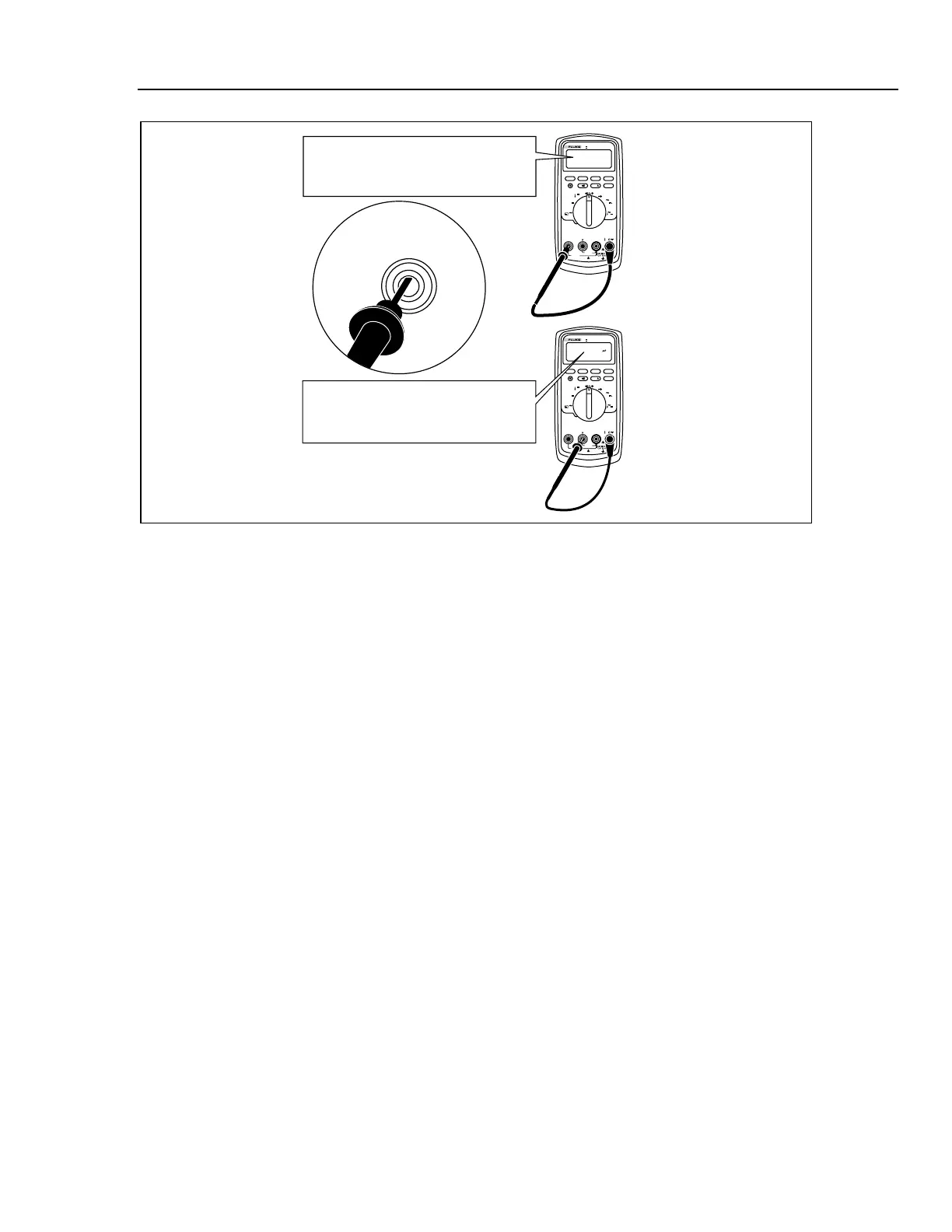
Good F2 fuse: 00.0 Ω to
00.5 Ω
Good F1 fuse: 0.995 kΩ to
1.005 kΩ
Replace fuse: OL
Replace fuse: OL
Touch top half
of input contacts
aom5f.eps
Figure 3. Testing the Current Input Fuses
Replacing the Fuses
To replace the fuse(s), perform the following procedure.
1. To open the Meter, refer to “Opening the Meter Case”. See Figure 1.
2. Grasp the fuse in the center with needle nose pliers. Pull straight up on the fuse to
remove it from the fuse clips.
3. Install ONLY specified replacement fuses with the amperage, voltage, and speed
ratings shown in Table 17.
4. To close the Meter, refer to “Reassembling the Meter Case”.
Required Equipment
Required equipment for the performance tests is listed in Table 13. If the recommended
models are not available, equipment with equivalent specifications may be used.
XW Warning
• To avoid shock or injury, do not perform the verification
tests or calibration adjustment procedures described in this
manual unless you are qualified to do so.
• Repairs or servicing should be performed only by qualified
personnel.

 Loading...