80 Series V
Calibration Manual
26
Notes
Set the calibrator to Standby prior to changing the function switch position
and or after completing adjustment of each function.
If the calibration adjustment procedure is not completed correctly, the
Meter will not operate correctly.
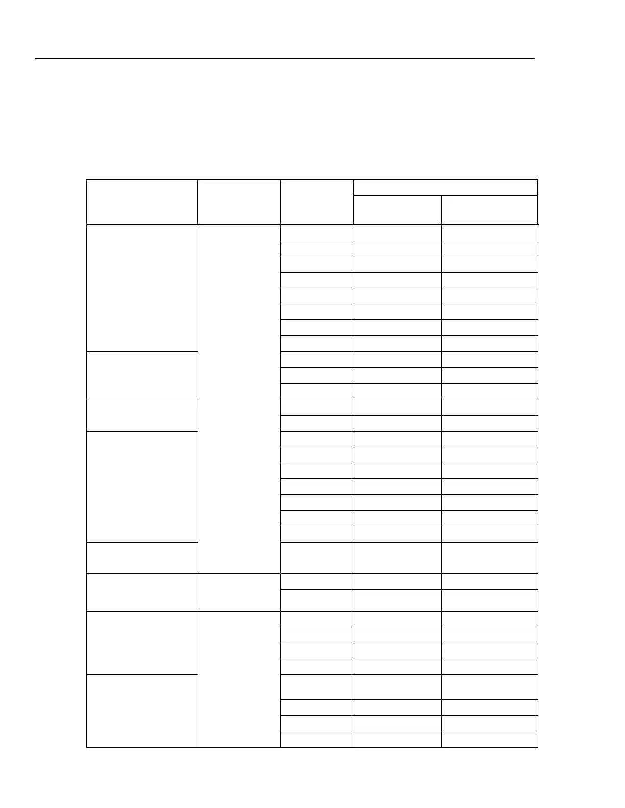
Table 16. Calibration Adjustment Steps
Input Value
Function
(Switch Position)
Input Terminal
Adjustment
Step
Fluke 83-V and
88-V
Fluke 87-V
C-01 600.0 mV, 60 Hz 600.0 mV, 60 Hz
C-02 600.0 mV, 5 kHz 600.0 mV, 20 kHz
C-03 6.000 V, 60 Hz 6.000 V, 60 Hz
C-04 6.000 V, 5 kHz 6.000 V, 20 kHz
C-05 60.00 V, 60 Hz 60.00 V, 60 Hz
C-06 60.00 V, 5 kHz 60.00 V, 20 kHz
C-07 600.0 V, 60 Hz 600.0 V, 60 Hz
K
(AC Volts)
C-08 600.0 V, 5 kHz 600.0 V, 10 kHz
C-09 6.000 V 6.000 V
C-10 60.00 V 60.00 V
L
(DC Volts)
C-11 600.0 V 600.0 V
C-12 600.0 mV 600.0 mV
m
L
(DC Millivolts)
C-13 60.00 mV 60.00 mV
C-14 600.0 600.0
C-15 6.000 k 6.000 k
C-16 60.00 k 60.00 k
C-17 600.0 k 600.0 k
C-18 6.000 M 6.000 M
C-19 0.000 0.000
e
(Ohms)
C-20 50.0 M 50.0 M
O
(Diode Test)
I
C-21 3.000 V 3.000 V
C-22 6.000 A, 60 Hz 6.000 A, 60 Hz
A
(Amps)
A
C-23 6.000 A dc 6.000 A dc
C-24 60.00 mA, 60 Hz 60.00 mA, 60 Hz
C-25 400.0 mA, 60 Hz 400.0 mA, 60 Hz
C-26 60.00 mA dc 60.00 mA dc
mA
(Milliamps)
C-27 400.0 mA dc 400.0 mA dc
C-28
600.0 µA ac,
60 Hz
600.0 µA ac, 60 Hz
C-29 6000 µA, 60 Hz 6000 µA, 60 Hz
C-30 600.0 µA dc 600.0 µA dc
µA
(Microamps)
mA /UA
C-31 6000 µA dc 6000 µA dc

 Loading...