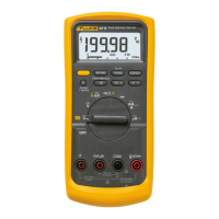
Digital Multimeter
Theory of Operation
9
Theory of Operation
This section provides the theory of operation for the 87 V/AN Digital Multimeter to a
depth that is required for troubleshooting to the component level. The functional block
diagram provides an overview for the description. The schematic diagrams included in
the manual are referred to during the following detailed circuit descriptions.
Functional Block Diagram
Figure 1 shows the top-level function block diagram for the Meter. Each of the blocks in
this diagram is discussed in detail in the following paragraphs.
The parameter to be measured is connected with test leads to the appropriate two input
terminals shown at the left of the block diagram. After the Meter is set to the desired
function, the signal is routed to the signal conditioning circuit. Either automatically or
manually, a range is selected that puts the signal to be measured within the dynamic
range of the analog-to-digital converter (ADC) or other signal conditioning circuits like
the RMS-to-DC converter discussed in “RMS to DC Converter”. A scaled AC signal
voltage is routed directly, or via an 800-Hz low-pass filter, to the RMS-to-DC converter
circuit. A DC input signal or DC output of the RMS-to-DC converter (for AC functions)
is routed to a low-pass, 6-Hz, 2-pole active filter to prepare it for ADC measurement.
The conditioned analog input signal voltage is converted to a digital value by the ADC
and sent to the microprocessor. The microprocessor converts this digital value for
display on the LCD based on the function, range and keypad entered options. The output
of the signal-conditioning block is also routed to the secondary analog circuits block to
be further conditioned for input to the fast ADC contained within the microprocessor
block. Other analog circuits that control the behavior of the Meter are located in the
secondary analog circuits block and are discussed later.

 Loading...