CERTIFIBER ENGLISH - 38
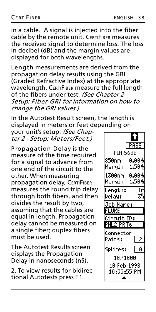
in a cable. A signal is injected into the fiber
cable by the remote unit. CERTIFIBER measures
the received signal to determine loss. The loss
in decibel (dB) and the margin values are
displayed for both wavelengths.
Length measurements are derived from the
propagation delay results using the GRI
(Graded Refractive Index) at the appropriate
wavelength. CERTIFIBER measure the full length
of the fibers under test. (See Chapter 2 -
Setup: Fiber GRI for information on how to
change the GRI values.)
In the Autotest Result screen, the length is
displayed in meters or feet depending on
your units setup. (See Chap-
ter 2 - Setup: Meters/Feet.)
Propagation Delay is the
measure of the time required
for a signal to advance from
one end of the circuit to the
other. When measuring
propagation delay, CERTIFIBER
measures the round trip delay
through both fibers, and then
divides the result by two,
assuming that the cables are
equal in length. Propagation
delay cannot be measured on
a single fiber; duplex fibers
must be used.
The Autotest Results screen
displays the Propagation
Delay in nanoseconds (nS).
2. To view results for bidirec-
tional Autotests press F1
All manuals and user guides at all-guides.com