11
8 % ≤ Duty Cycle < 10 %, Maximum current = 6 A
10 % ≤ Duty Cycle ≤ 85 %, Maximum current = (duty cycle %) x 0.6
85 % < Duty Cycle ≤ 96 %, Maximum current = (duty cycle % - 64) x 2.5
96 % < Duty Cycle ≤ 97 %, Maximum current = 80 A
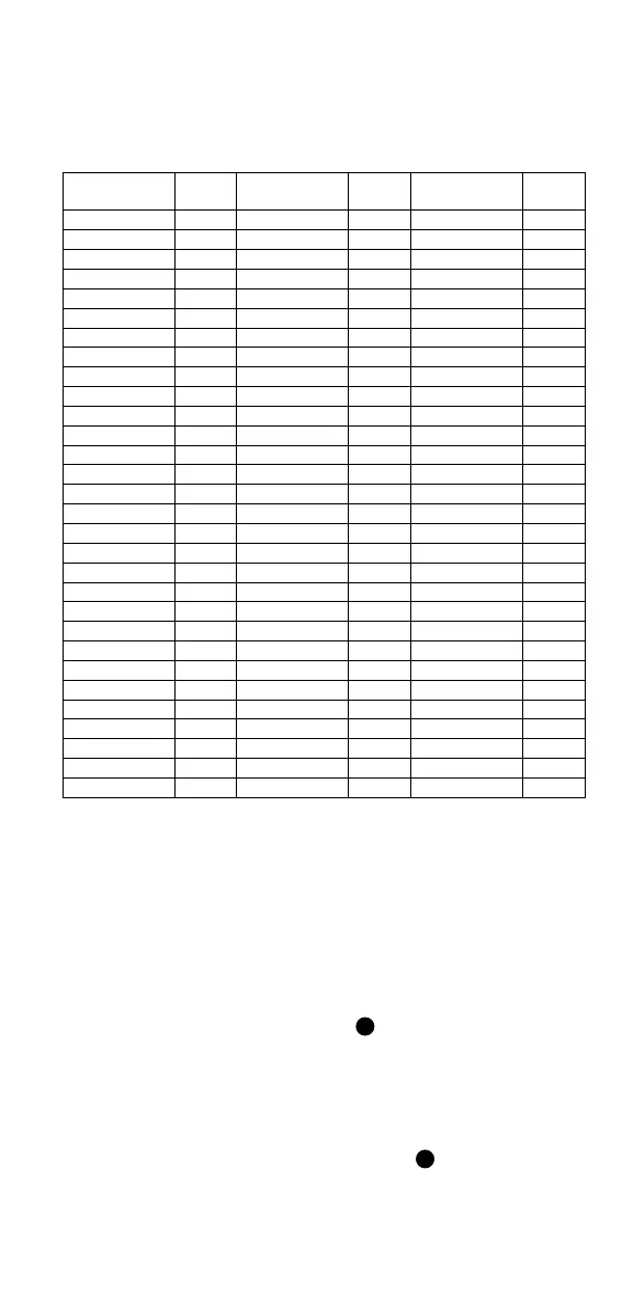
See detailed calculations in Table 4.
Table 4. Calculations of max. charging current on basis of duty cycle.
Duty Cycle (%)
Max
Amps
Duty Cycle (%)
Max
Amps
Duty Cycle (%)
Max
Amps
8 6.0 40 24.0 70 42.0
10 6.0 41 24.6 71 42.6
11 6.6 42 25.2 72 43.2
12 7.2 43 25.8 73 43.8
13 7.8 44 26.4 74 44.4
14 8.4 45 27.0 75 45.0
15 9.0 46 27.6 76 45.6
16 9.6 47 28.2 77 46.2
17 10.2 48 28.8 78 46.8
18 10.8 49 29.4 79 47.4
19 11.4 50 30.0 80 48.0
20 12.0 51 30.6 81 48.6
21 12.6 52 31.2 82 49.2
22 13.2 53 31.8 83 49.8
23 13.8 54 32.4 84 50.4
24 14.4 55 33.0 85 51.0
25 15.0 56 33.6 86 55.0
26 15.6 57 34.2 87 57.5
27 16.2 58 34.8 88 60.0
28 16.8 59 35.4 89 62.5
29 17.4 60 36.0 90 65.0
30 18.0 61 36.6 91 67.5
31 18.6 62 37.2 92 70.0
32 19.2 63 37.8 93 72.5
33 19.8 64 38.4 94 75.0
34 20.4 65 39.0 95 77.5
35 21.0 66 39.6 96 80.0
36 21.6 67 40.2 97 80.0
37 22.2 68 40.8
38 22.8 69 41.4
Error states:
Duty Cycle = 0 % (Duty Cycle < 3 %), State F or E (see IEC/EN 61851-1
Standard); no charging allowed
Duty Cycle = 5 % (4.5 % ≤ Duty Cycle ≤ 5.5 %), Indicates that digital
communication is needed
7 % < Duty Cycle < 8 %, Error state; no charging allowed
Duty Cycle = 100 %, State B1, C1 or D1; no charging allowed
CP Error state “E” simulation
Use CP Error “E” button (see Figure 2, item
9
) to simulate a CP Error. When
CP Error state “E” is pushed, the test adapter makes a short circuit between
CP and PE through internal diode. As a result, the pending charging process is
aborted and new charging processes are prevented.
PE Error state "F" (Earth Fault) simulation
Use the PE Error state "F" button (see Figure 2, item
8
) to simulate an
interruption of the PE conductor. The pending charging process is aborted and
new charging processes are prevented.