Do you have a question about the Fluke FTK200 and is the answer not in the manual?
Instructions for cleaning fiber ends before making connections using swabs or canned air.
Lists key features of the FTK200 Optical Fiber Test Kit, including measurements, saving, and PC connectivity.
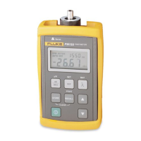
Details the features of the FM150 Fiber Meter based on Figure 2, numbering specific buttons and displays.
Step-by-step guide to measure optical power, including setting wavelength, cleaning, connecting, and verifying units.
Guidelines on when to set a reference for accurate loss measurements, such as changing sources or patch cords.
Detailed steps to set a reference for loss measurements, including connecting equipment, selecting wavelength, and holding the REF button.
Steps to measure optical power loss, including setting reference, cleaning, connecting, and verifying dB unit.
Emphasizes using the same patch cords for loss measurement as used for setting the reference.
How to save current readings, record details, and review saved measurements using the RECALL button.
Steps to overwrite existing saved measurements with new readings using the STORE key.
How to delete all saved measurements for a specific wavelength or all wavelengths.
Instructions on cleaning the meter case with a soft cloth and mild detergent, avoiding solvents.
Guidance on replacing the battery in the FM150 Fiber Meter and FS150 Fiber Source based on indicators.
Lists available accessories and replacement parts for the FTK200 kit with their corresponding Fluke model or part numbers.
Specifies the detector type (Germanium) and calibrated wavelengths (850, 1300, 1310, 1550 nm).
Details the measurement range (+6 dBm to -50 dBm) and resolution (0.01 dB) for the FM150 Fiber Meter.
Provides loss/power measurement accuracy, operating and storage temperature, and humidity ranges.
Information on battery type/life (9V alkaline, 30 hrs) and low battery indication (BAT).
Details memory capacity (500 measurements) and serial port connector type (3.5mm phone jack).
Lists certifications (CE) and physical dimensions (3.2x5.8x1.5 in) of the FM150 Fiber Meter.
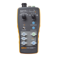
Specifies the light source (Infrared LED) and operating wavelengths (850 nm, 1300 nm).
Details output power (-20 dBm nominal) and connector type (ST) for the FS150 Fiber Source.
Provides stability rating (±0.1 dB/8 hours) and battery type/life (9V alkaline, 30 hrs).
Lists temperature range, humidity, and certifications (CE) for the FS150 Fiber Source.
Details serial port functionality, interface cable configuration, and pin assignments for serial communication.
Table showing pin assignments for the serial cable (Tip, Ring, Sleeve) and their corresponding signals.
Step-by-step instructions to send measurements directly to a serial printer using the RS-232 cable.
Instructions to send measurements to a PC using the provided LinkWare™ software.
Defines terms like Adapter, Attenuation, Core, dBm, Insertion loss, and Launch cable.
Defines terms like Macrobending losses, Microbending losses, Multimode fiber, Optical power, Receive cable, SC connector, Singlemode fiber, ST connector, Test Jumper.
| Brand | Fluke |
|---|---|
| Model | FTK200 |
| Category | Test Equipment |
| Language | English |