Hardware
Functional
Description
Front
Unit
LCD Drivers
U201
Driver 1
PCF8576
SCL
—
E>
<
—
<K>-
FC-bus
1
SDA
—
1>
Y
Sync.
U202
Driver 2
PCF8576
BackpL 0
Backpl. 1
LCD
158 segments
2:1
Multiplex
Figure
4-2
Front panel
LCD drivers.
The front
unit
is made of a moided
aluminum front. The
keypad is
made
of siiicon rubber
with
screened carbon
pads on a PC
board that covers
the
total front. An LCD
and four LED’s
are used as indicators.
To
show both the
measurement
result
and the state
indicators
of
the instru-
ment
setting
a LCD
is
used. The LED’s shows
standby,
ga-
ting,
and
triggering channel A
and B.
It has 160
segments that are
multiplexed
with a ratio of
2:1. Two cascade
coupled LCD drivers (U201
and U202)
are used. A
serial
l^C bus connects the
drivers to the p-
controller on
the
main board. R201
sets the clock frequen-
cy of the
drivers
to approximately 140
kHz.
The VLCD pin
is connected to
GND on
the
main board.
A back-light is
provided
with
the
LCD. This is an
LED array
integrated to one
component,
it
uses approximately
0.35 A
and dissipates
approximately 1 .5 W.
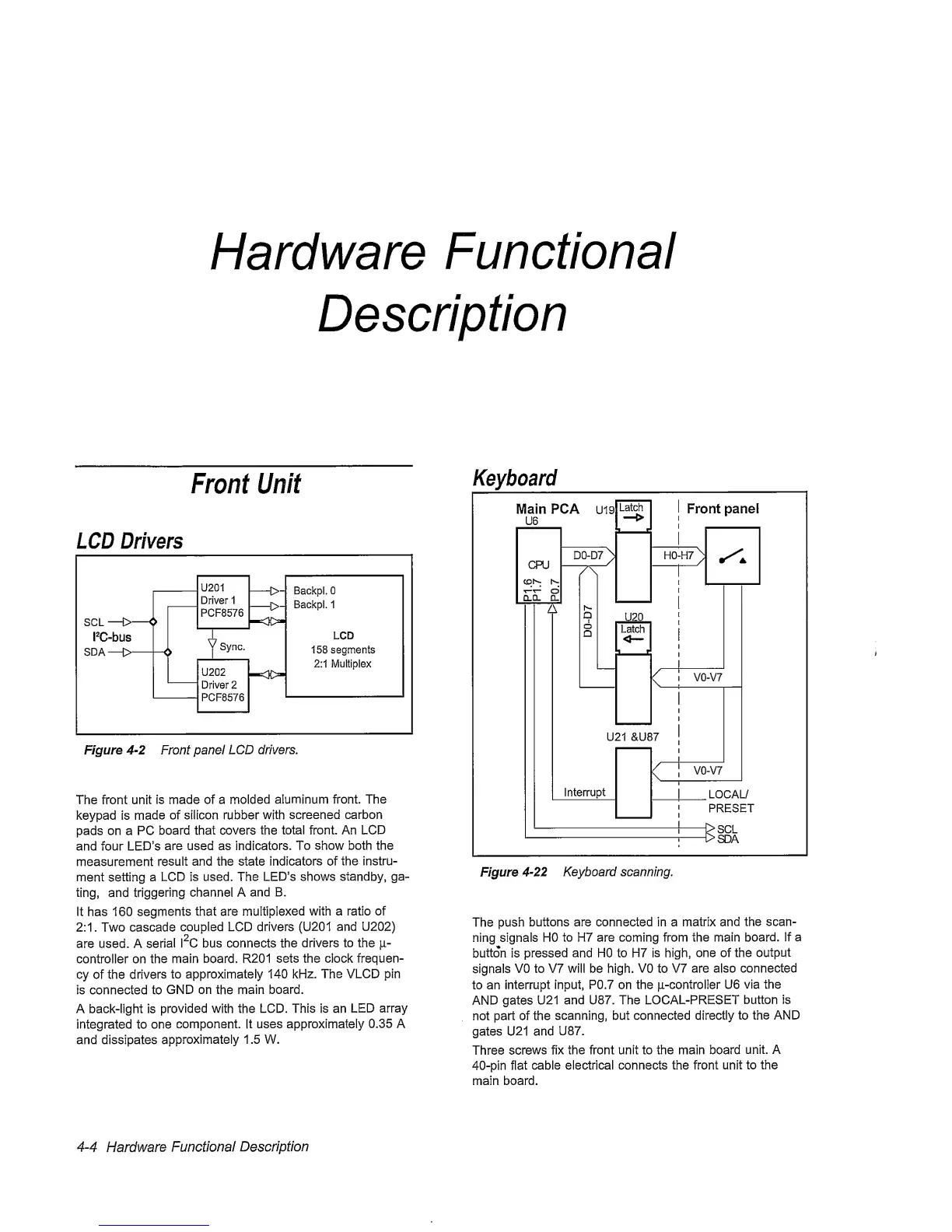
Keyboard
Figure
4-22
Keyboard scanning.
The push
buttons are connected in a matrix
and
the scan-
ning signals HO
to H7 are coming from the main
board.
If a
button is pressed and HO to H7
is high,
one of the
output
signals
VO to V7 will be high. VO to
V7 are also connected
to an
interrupt
input, P0.7 on the jiL-controller U6
via the
AND gates U21
and U87. The
LOCAL-PRESET
button is
not part of the
scanning, but connected directly
to
the AND
gates U21 and
U87.
Three
screws
fix the front unit to the main board
unit. A
40-pin
flat
cable electrical connects the front
unit
to the
main board.
4-4
Hardware
Functional
Description