Microcomputer Kernel
(Functional
Level
4a)
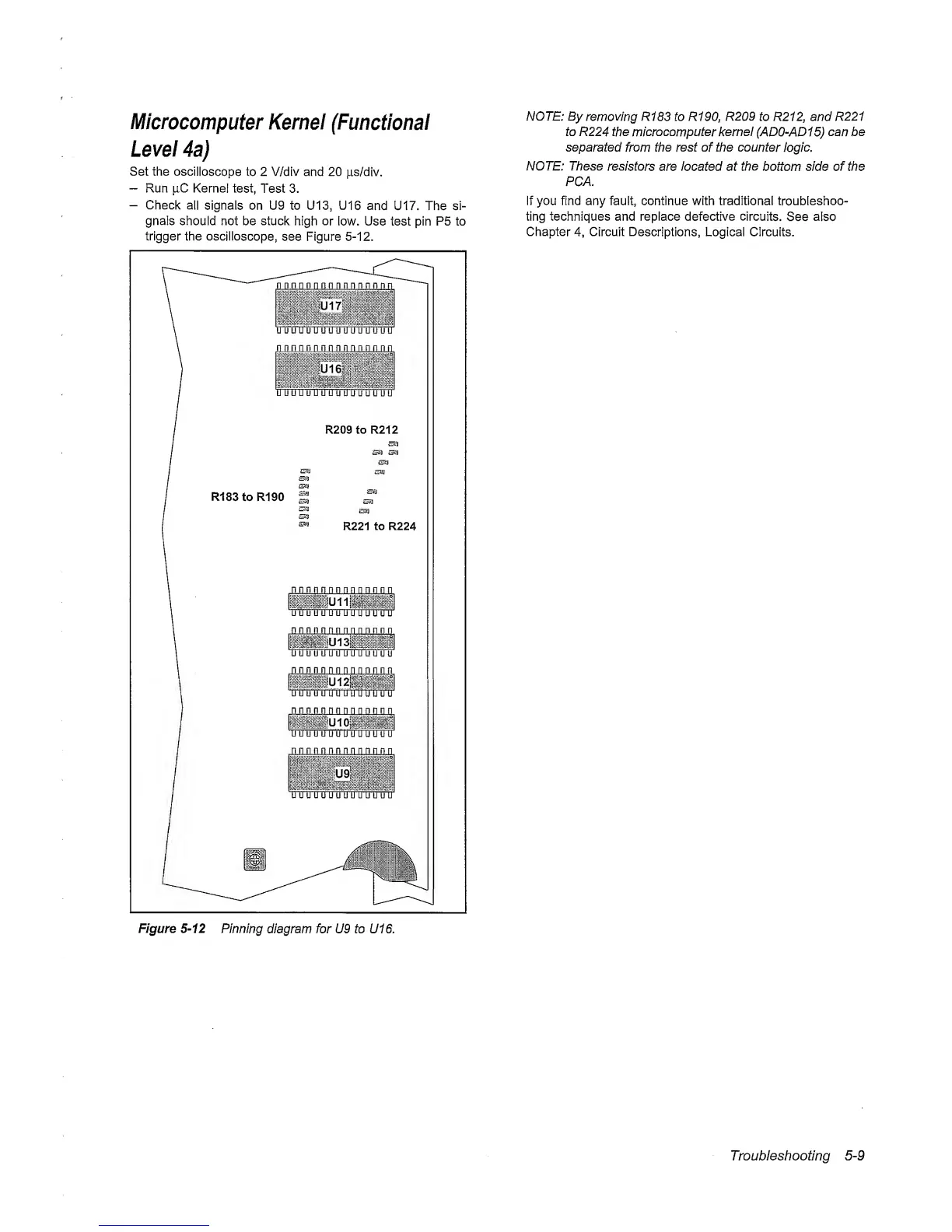
Set the
oscilloscope
to 2 V/div and
20
jxs/div.
“
Run jiC Kernel
test,
Test 3.
-
Check
all
signals on U9 to U13, U16
and U17. The si-
gnals should not be stuck
high or
low. Use test pin P5 to
trigger the oscilloscope,
see Figure
5-12.
NOTE: By
removing
R183 to R190, R209 to R212, and R221
to R224 the
microcomputer
kernel
(AD0-AD1
5)
can be
separated
from
the rest
of
the counter
logic.
NOTE: These
resistors
are located at
the
bottom side of the
PCA.
If you find any fault, continue with traditional troubleshoo-
ting techniques and replace
defective
circuits.
See also
Chapter
4,
Circuit Descriptions,
Logical Circuits.
Figure
5-12
Pinning
diagram for U9 to U16.
Troubleshooting
5-9