•
Prescaler 2.
7
GHz, PM
9624
See
Chapter
2,
Performance
Check, for verification.
Figure
5-26
Specified and typical
sensitivity
of input C
with
option PM 9624,
This prescaier cannot be
repaired in a local workshop.
It
must be sent to a Fluke
Service Center,
who will transfer
the prescaler to the factory for repair.
•
Prescaler
4.2 GHz, PM
9625B
See Chapter
2,
Performance
Check, for
verification.
Figure
5-27
Specified
and
typical sensitivity of input C
with
option PM 9625B,
This prescaler
cannot be
repaired
in
a local workshop. It
must
be
sent to a Fluke
Service Center, who will
transfer
the prescaler
to the factory for
repair.
•
Prescaler
4.5
GHz, PM
9625
See
Chapter
2,
Performance
Check, for
verification.
Frequency
Figure
5-29
Specified and
typical sensitivity of input
C
with option PM
9625.
This prescaler
cannot be
repaired
in a local workshop.
It
must be sent
to a Fluke
Service Center, who will transfer
the
prescaler to
the factory for
repair.
GPIB
interface and
Analog output
(Functional
Level
10)
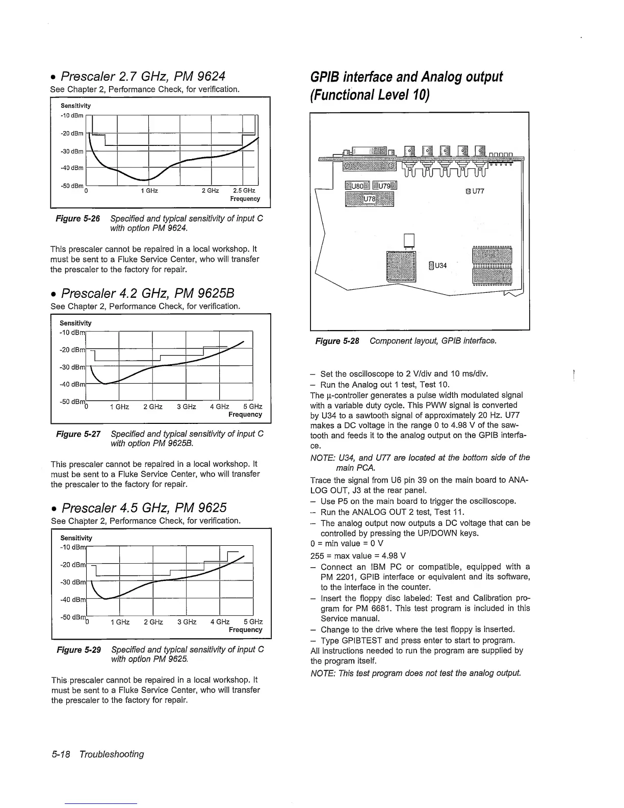
Figure
5-28
Component
layout, GPIB
interface.
-
Set
the
oscilloscope to 2
V/div
and 10 ms/div.
-
Run the
Analog out 1 test, Test
10.
The
ji-controlier
generates a pulse
width
modulated signal
with a
variable
duty cycle. This
PWW signal is converted
by U34
to a sawtooth
signal of
approximately 20
Hz.
U77
makes a
DC voltage in the range 0
to
4.98 V of the
saw-
tooth
and feeds it to
the analog
output on the
GPIB
interfa-
ce.
NOTE: U34,
and U77 are located at
the bottom side of
the
main PCA.
Trace the signal from
U6 pin 39 on the main
board
to ANA-
LOG OUT, J3
at the rear panel.
-
Use P5 on
the main board to trigger
the oscilloscope.
-
Run the
ANALOG
OUT 2 test. Test 1 1
.
-
The analog
output now outputs a DC
voltage
that can be
controlled by
pressing the UP/DOWN keys.
0
=
min value
=
0
V
255
=
max value
=
4.98 V
-
Connect
an IBM
PC
or compatible, equipped
with a
PM
2201,
GPIB
interface or equivalent
and
its software,
to
the interface in
the counter.
-
Insert
the floppy disc
labeled: Test
and Calibration
pro-
gram for
PM
6681. This test program is
included in this
Service
manual.
-
Change to
the drive where the test floppy
is inserted.
-
Type
GPIBTEST and press
enter
to start to program.
All
instructions
needed to run the program
are supplied by
the program
itself.
NOTE:
This
test program
does not test the
analog
output.
5-18
Troubleshooting