DC-voltages
“
Use a DMM to measure
the
DC-levels
according
to
Table
5-8.
Test point
Measured
voltage
IC1
pin
1
«0.9
V
IC1 pin 5
-3.1
V
TS1 pin b
-
1.6 V
TS1 pin c
-3.1
V
TS2 pin
e
-2.3
V
IC2 pin
2,3 -
1.5
V
IC2
pin
6,7
-4.5 V
TS5;c
-4.5
V
TS6;c
-4.5
V
BUT pin 4
-4.7
V
TPS
-
0.57 V
Table
5-8
DC voltages, PM
9621.
-
Connect the signal generator to
the
HF input of the
counter.
-
Set
the
input frequency to 100 MHz and
set the amplitu-
de to
-15
dBm,
(40
mVRMS).
-
Connect the oscilloscope to BUT
pin 4.
-
Verify that
the amplitude
is 800 mV
p-p
and
that
the pe-
riod time is
2.56
\is, (frequency
390
kHz). The DC level
should be 3.8 V.
If everything
seems all right
the fault is
probably caused by
the base
unit.
“
Connect the DMM to TP3
and
TP4 (GND).
-
Disconnect
the
input signal.
-
Check that the DC
voltage
drops
~
200 mV.
If this last measurement is OK,
you can skip the Overvolta-
ge Protection Control.
Overvoltage
Protection Control
-
Connect the signal generator to
the
HF input of the
counter.
-
Set the
input frequency
to 100 MHz, and set
the
amplitu-
de to 13 dBm,
(1
Vrms).
-
Check the DC
voltages
according to
0.
Test point
Measured
voltage
Comment
TP1
-100
+50
mV
Correct
TP1
-
+300
mV
GR3 faulty
TP1
-
-300
mV
GR4 faulty
TP2
-220
+100
mV
Correct
TP2
-
-400
mV
GR11 faulty
TP1 & TP2
-
+50
mV
Short circuit in one
of GR3, GR4 or
GR11
Table
5-9
DC voltages, Overvoltage
protection control,
PM 9621.
-
Connect the DMM to IC2 pin 2.
-
Check that the DC voltage
is
-
300 mV.
-
Check that the
amplitude
at 1C1 pin 1 is
one
third
of the
amplitude at BUI.
-
Check that the amplitude
at 1C1 pin 5 is
==
300 mVp-p.
-
Check that the amplitude at TS1
collector
and TS2 emit-
ter is 500 mVp-p.
Level Detector Control
-
Disconnect the
signal generator
from the
counter.
-
Check the level detector according to the table below.
-
Connect the signal generator to
the
HF
input of
the
counter.
-
Set the input
frequency
to
100
MHz and
the
amplitude to
13 dBm,
(1
Vrms).
-
Check
the
level detector according
to
Table
5-10.
Test point Without input
signal
With input
signal
GR7, Cl 6 -
320
mV
-
10
mV
1C3 pin 3 -
570 mV
=
370
mV
ICS pin
1
,
6
-2.2
V
<0.1 V
1C3 pin 5 -
2.07 V
-2.1 V
ICS
pin
7
<
0.8
V
-4.4
V
TS8;b
-4.9
V
-4.2
V
BUT
pin
4
-4.7
V
-3.8 V
Table
5-10
DC voltages, Level
detector,
PM 9621.
Divider
and Differential Stage Control
-
Connect
the oscilloscope to IC2
pins
6 and
7.
“
Check that the amplitude is 800 mVp-p and that the pe-
riod time
is
2.56
[is, (frequency 390
kHz).
The
DC level
is 4.5
V.
-
Connect the oscilloscope to TS3;b and TS4;b.
-
Check that
the amplitude
is 800
mVp-p
and that the pe-
riod time is
2.56
\is, (frequency 390
kHz).
The
DC
level
is 3.8
V.
-
Connect
the
oscilloscope
to TS5;c
and TS6;c.
-
Check
that
the amplitude is 800
mVp-p and that the
pe-
riod time is
2.56
[is, (frequency 390 kHz). The DC level
is
4.5
V.
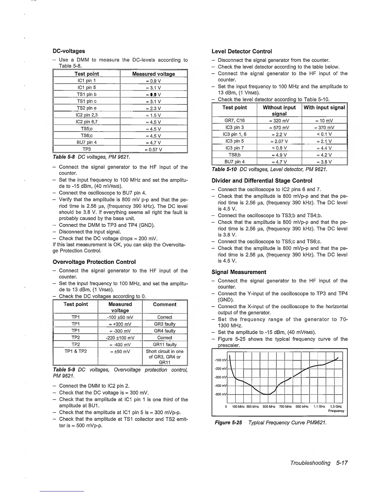
Signal
Measurement
-
Connect the signal
generator
to the HF input of the
counter.
-
Connect
the Y-input of the oscilloscope
to TP3 and TP4
(GND).
-
Connect
the
X-input of the
oscilloscope
to the horizontal
output of the generator.
-
Set the frequency range of the generator to
70-
1300 MHz.
-
Set the amplitude to
-15
dBm,
(40
mVRMS).
-
Figure
5-25
shows the typical frequency curve of the
prescaler.
Figure
5-25
Typical Frequency Curve PM9621.
Troubleshooting
5~17
 Loading...


