Crystal Oscillators
16
MHz
Oscillator
-
Connect the counter via a probe to the test point P7
and
GND5.
-
Check that the measured frequency is 8 MHz
±100
Hz.
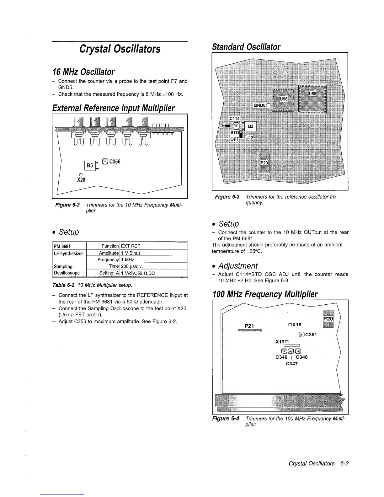
External Reference Input
Multiplier
Figure
6-2
Trimmers for the 1 0 MHz Frequency Mulfh
plier.
standard Oscillator
Figure
6-3
Trimmers for the reference oscillator fre-
quency.
•
Setup
PWI 6681
Function EXT REF
LF
synthesizer
Amplitude
1
V
Sinus
Frequency 1 MHz
Sampling
Oscilloscope
Time
200 fis/div.
Setting: A
1
V/div.,50
n,DC
Table
6-2
10 MHz Multiplier setup.
—
Connect the LF synthesizer to the REFERENCE
iNput at
the rear of the PM 6681
via
a
50
O
attenuator.
—
Connect the Sampling Oscilloscope to the test
point
X20.
(Use a FET probe).
—
Adjust C356 to maximum amplitude. See
Figure
6-2.
•
Setup
-
Connect the counter to the 10 MHz OUTput at the
rear
of the PM 6681.
The adjustment should
preferably be
made at
an
ambient
temperature
of
+25°C.
•
Adjustment
-
Adjust C114=STD OSC
ADJ until the
counter reads
10
MHz
+2
Hz. See
Figure
6-3.
100
MHz
Frequency
Multiplier
Figure
6-4
Trimmers for the 100 MHz
Frequency Multi-
plier.
Crystal
Oscillators
6-3