•
Setup
PM
6681
Function EXT REF
LF
synthesizer
Amplitude 1
V
Sinus
Frequency 10 MHz
Sampling
Oscilloscope
Time
200
M-s/div.
Setting:
A
1
V/div.,50
a, DC
Table
6-3
100
MHz
Multiplier
setup.
-
Connect
the Sampling
Oscilloscopes
trigger input to the
10 MHz OUT at the rear of the counter.
-
Connect
the Sampling
Oscilloscope
via a probe to the
test point
XI 9. See Figure
6-4.
-
Adjust the capacitor C346 to 10 cycles/100 ns.
-
Connect the Sampling Oscilloscope to the
test
point XI 8.
-
Adjust the
capacitors
C347,
C348, and C351 to maxi-
mum
amplitude.
-
Adjust the capacitors C346, C347, C348,
and C351 to
maximum
amplitude
In
sequence
until maximum amplitu-
de is reached at X18.
-
Connect the LF-synthesizer with a 10
MHz reference to
the EXT-REF input of the counter.
-
Select EXT REF.
-
Change the input frequency ±1 kHz.
if
the amplitude is varying with the frequency
the capacitors
C347
and
C348
has to be adjusted again. Begin to
adjust
the
the
amplitude at 10 MHz
+1
kHz.
Eventuality C346
has
to adjusted as well.
Optional
TCXO, PM
9678B
•
Setup
-
Connect the counter to the
line
power.
“
Switch
on the counter.
-
Press PRESET, then
press
ENTER.
“
Connect
the 10 MHz reference
to the
A input of the
counter.
The adjustment
should
preferably be made at an
ambient
temperature
of +23°C.
•
Adjustment
-
Adjust the
trim capacitor C1 on the
optional
oscillator un-
til the
counter reads 10
MHz
+1
Hz.
See Figure
6-5.
Optional
Oven Oscillators,
PM 9690
and
PM 9691
•
Setup
“
Connect
the
counter to the line power.
—
Switch on the
counter.
—
Press
PRESET, then press ENTER.
I
Oscilloscope
Time lOOns/div.
Table
6-4
Optional oscillator setup.
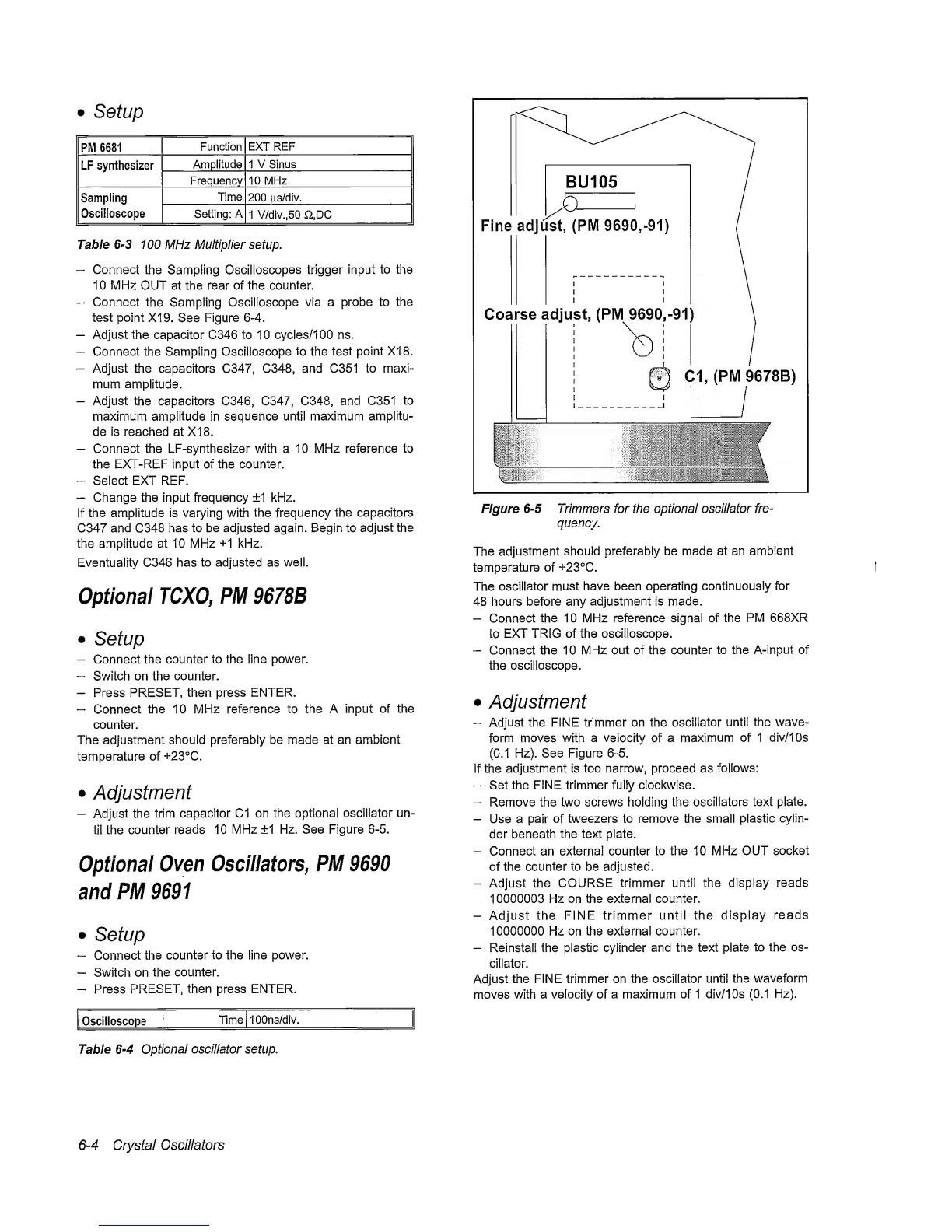
Fine adjust,
(PM
9690,-91)
Cl, (PM
9678B)
Figure
6-5
Trimmers for the optional oscillator
fre-
quency.
The
adjustment
should preferably be made at an
ambient
temperature
of +23°C.
The
oscillator
must have been operating
continuously
for
48 hours before any
adjustment is made.
-
Connect
the 10 MHz reference signal of the
PM
668XR
to
EXT TRIG of the oscilloscope.
-
Connect the 10 MHz out of the
counter to the A-input of
the
oscilloscope.
•
Adjustment
-
Adjust the FINE trimmer on the
oscillator
until the wave-
form moves with a velocity of a
maximum
of 1 div/IOs
(0.1
Hz). See Figure
6-5.
If the
adjustment is too narrow, proceed as
follows:
-
Set the FINE trimmer fully clockwise.
~
Remove the two screws holding the
oscillators text plate.
-
Use a pair
of
tweezers to remove the small
plastic
cylin-
der beneath
the text plate.
-
Connect an
external counter
to the 10 MHz OUT
socket
of
the counter to be
adjusted.
-
Adjust the
COURSE
trimmer until the display
reads
1
0000003 Hz on the external
counter.
-
Adjust the
FINE trimmer
until the display
reads
10000000 Hz on the external
counter.
-
Reinstall the plastic
cylinder
and the text plate
to
the os-
cillator.
Adjust
the FINE trimmer on the oscillator
until
the waveform
moves
with
a velocity of a maximum of 1
div/IOs
(0.1
Hz).
6-4
Crystal
Oscillators
 Loading...


