Interpolator
NOTE:
This adjustment has only to be performed if the ti-
mer/counter
has
lost its caiibration
information, (that
is
If the counter displays zc a l . l o
s
t z, or /f you
have
made any repairs in the interpolator circuits.
•
Setup
~
Connect the Pulse Generators output A to the input A of
PM
6681.
-
Connect the LF-synthesizers to the EXT INput of the
Pulse Generator.
—
Connect a 10 MHz
(aging at least
10'®)
reference to
the
reference input of PM 6681 and the synthesizer.
-
Connect the the GPIB connectors of the PM
6681,
LF-
synthesizer,
and Pulse Generator to
the
PC;s
GPIB
card.
NOTE: The timer/counter,
synthesizer,
and
the pulse gener-
ator should not have the same GPIB address, none of
them should have address 0 or
30,
(this is used by the
PC).
•
Adjustment
—
Turn on the timer/counter, the synthesizer, and the pulse
generator.
If
the timer/counter shows
a flashing zcal.lostz, press
the preset button
until this
message
disappears.
NOTE: The calibration should be done when the counter has
been on for more than 20 minutes. If you start the ca-
libration program before 20 minutes has passed since
power on, the program will wait the required time.
“
Insert the discette labeled "Test
and Calibration program
for PM
6681",
into the 3 V
2
"
disc-drive on the PC.
-
Start the calibration program from
the
DOS
command
prompt with the command
"[path]CALVER81".
Suppo-
sing you use the A: drive, this might look like:
C:\ >a:CALVER81
The first displayed
screen
on the PC will show you the
nee-
ded hardware and software to run the
calibration program.
It also shows the bus addresses the different
instrument
must be set to.
-
Press ENTER when you are
ready
to begin the calibra-
tion.
-
Now you shall enter the different
GPIB
addresses for the
instruments involved.
-
Type the
serial number
of the counter under
test
and
press ENTER.
Now you will be asked if you want to
calibrate the
counter.
The calibration will take between 20 and 60
minutes
to
complete.
(If you
answer no
(n)
on this question you will
be
asked
if you want to verify
the
calibration of the interpola-
tors. The verification will only
take
a few minutes.)
The program will attempt
calibration
using a number of dif-
ferent input signals, and will check
the result, choosing for
the final calibration the best result achieved.
After
the
calibration is
completed
the best calibration para-
meter will be stored in the counters
battery
backuped
RAM. A printout of the calibration
result will
also be sent to
LPT1
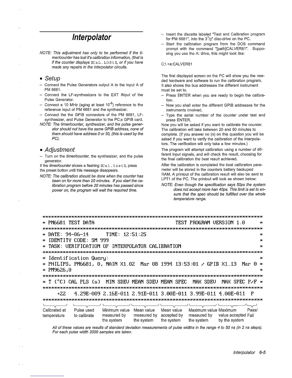
of the PC. The printout
will
look
as shown below:
NOTE: Even though the specification says
50ps the system
does not accept more han 40ps.
This limit is set to en-
sure that
the spec should
be
fulfilled over the
whole
temperature range.
*
PM6681 TEST
DATA TEST
PROGRAM
UERSIOM 1.0
^
DATE:
94-06-14
TIME:
12:51:25
^
IDEMTITV CODE: SM 999
^
TASK: UERIFICATIOM OF INTERPOLATOR CALIBRATIOM
*
*
*
*
Identification Query:
*
*
PHILIPS. PM6681.
0.
MAIM XI. 02 Mar 08 1994
13:53:01
/ GPIB XI. 13
Mar
0
^
^
PM9626.0
^
*
T C°CD
CAL
PLS CsD MIN SDEU MEAN SDEO MEAN SPEC MAX
SDEU
MAX
SPEC P/F
^
+22
4.29E-009 2.16E-011 2.91E-011 3.00E-011 3.99E-011 4.00E-011 P
Calibrated at Pulse used Minimum value Mean value Mean value Maximum value Maximum
Pass/
temperature to
calibrate
measured by
measured
by
accepted
by
measured
by
value
accepted
Fail
the system the system the system the system by the
system
All of these values are results of standard deviation measurements of pulse widths in the range 4 to 50 ns
(in 2 ns
steps).
For each pulse
width 2000
samples
are taken.
Interpolator
6-5
 Loading...


